RE-HOBI362 Rachel Hoffman-Bice, PhD
Seek & Geek

Seek & Geek 4: The YuMi Collaborative Robot

HTMs for Dummies — building the transform chain for a 7-DOF arm, then adding the errors

Period Week 4

This week I got to look at the YuMi collaborative robot one of my labmates uses for his research. YuMi is ABB’s dual-arm small-parts assembly robot, designed from the start to be safe enough to work side by side with people.
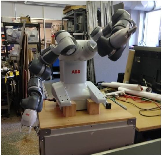
The ABB YuMi robot standing on wooden blocks on a workbench in the lab, both arms raised, with lab equipment and shelving behind it

My real reason for choosing it was to get more insight into homogeneous transformation matrices — how they’re used to predict the error at a robot’s end effector.

Each YuMi arm has seven degrees of freedom, not counting the gripper, which makes it extremely versatile inside a human-sized workspace.
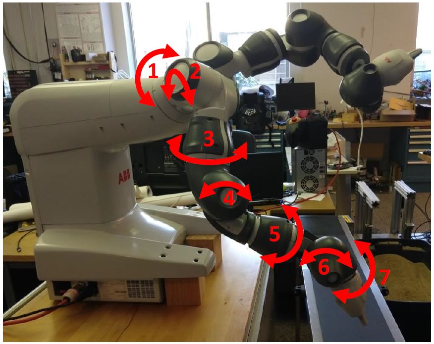
The YuMi arm photographed in the lab with each of its seven revolute joints marked by a numbered red rotation arrow, from 1 at the shoulder through to 7 at the wrist

Bear with me, because HTMs involve a lot of maths. But I’m hoping this can turn into a sort of “HTMs for Dummies” that other people who are stuck can use as a guide.

Setting up the frames

Start by defining the reference coordinate system at the base of the first revolute joint, then define successive coordinate systems at the centre of each remaining joint travelling down the arm, ending at the end effector.
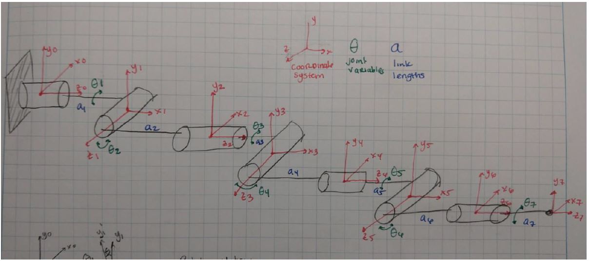
Hand-drawn diagram of the seven-link arm as a chain of cylinders, each with its own red coordinate triad x-i, y-i, z-i, green joint variable theta-i and blue link length a-i, from frame 0 at the wall mount through to frame 7 at the end effector

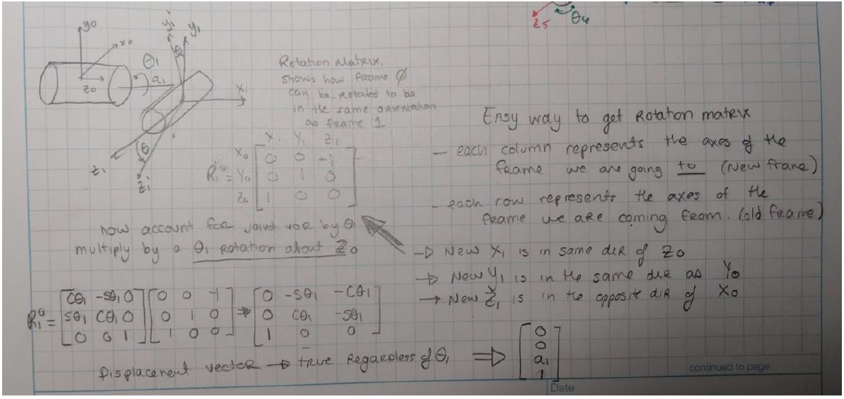
The rotation matrix, the easy way

Handwritten derivation of the first rotation matrix with the note that it shows how frame 0 can be rotated into the same orientation as frame 1. Two rules are boxed: each column represents the axes of the frame being transformed to, each row the axes of the frame being transformed from. The joint variable is then accounted for by multiplying by a theta-1 rotation about z-0, and the displacement vector is noted as true regardless of theta-1

The trick that made this click for me is that simple rule about columns and rows — each column is an axis of the frame you are going to, each row an axis of the frame you are coming from. Then account for the joint rotating by multiplying by a rotation about the previous frame’s z axis.

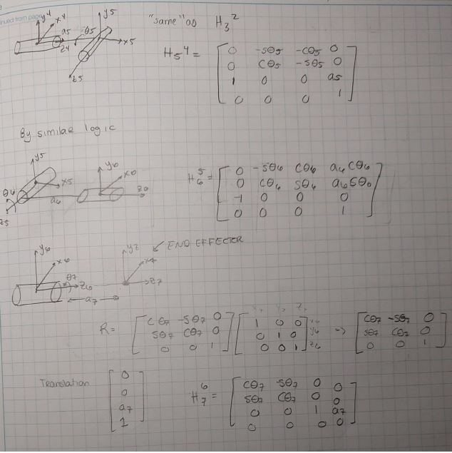
The same logic gives every successive transformation down the arm.
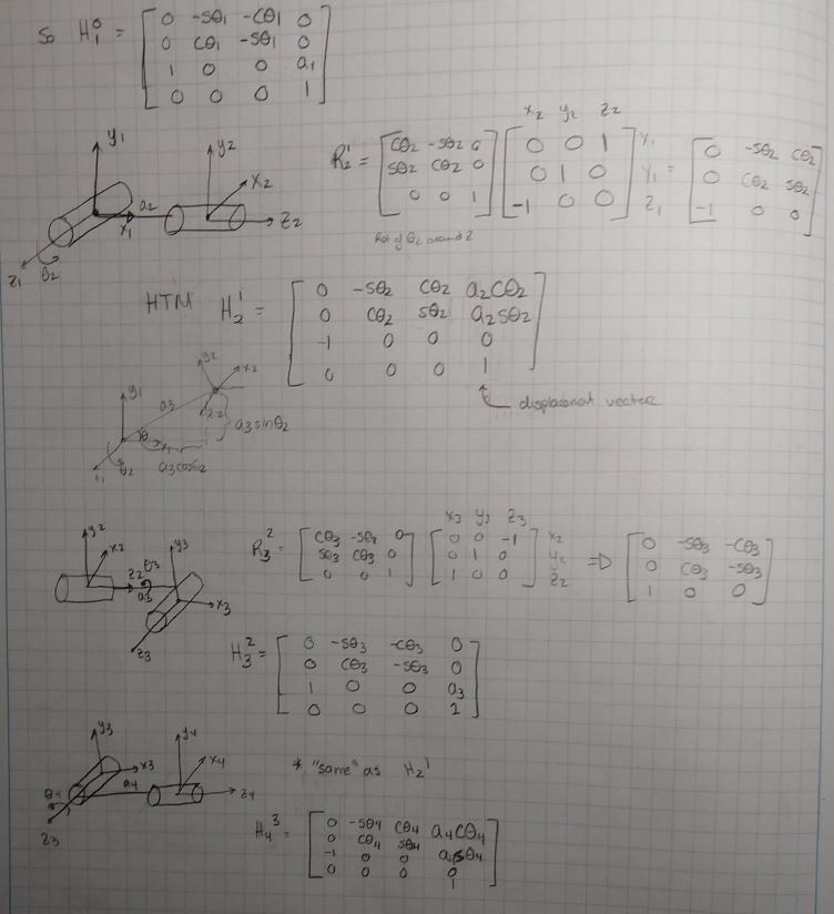
Handwritten derivations of the transforms from frame 0 to 1, 1 to 2, 2 to 3 and 3 to 4, each with its sketch of the two frames, its rotation matrix built from the column-and-row rule, and the resulting 4 by 4 homogeneous matrix including the displacement vector

Continued derivations for frames 4 to 5, 5 to 6 and 6 to 7, the last labelled END EFFECTOR, each with its sketch, rotation matrix and translation

Multiply them together in series and you have the complete transformation carrying end effector coordinates back into the reference frame.
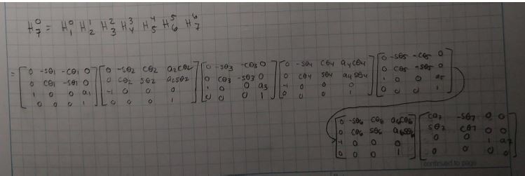
The full chain written out as H-0-7 equals the product of all seven successive homogeneous transformation matrices, each 4 by 4 and written in terms of sines and cosines of its joint angle and its link length

The calculation is genuinely lengthy, so I haven’t included the full expansion — but it is easy to code symbolically in MATLAB, and I’d strongly suggest doing that for future work.

Adding the errors

Reading the HTM section of Precision Machine Design (Ch. 2.2), what helped most was considering each error on its own and then building them all up into a single error matrix. The text describes the process, but it only really landed once I did the calculations myself in MATLAB.

The insight: think of it as first transforming into the new coordinate system, then transforming that new system into the same system as affected by errors.
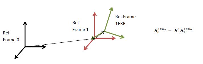
Diagram showing reference frame 0 in black, the ideal reference frame 1 in red, and the error-affected frame 1ERR in green offset from it, with the relation H-0-1ERR equals H-0-1 times H-1-1ERR

The errors themselves are three translational (δx, δy, δz) and three rotational (εx, εy, εz). Each becomes its own elementary transform, and multiplying the six together gives the total transformational error.
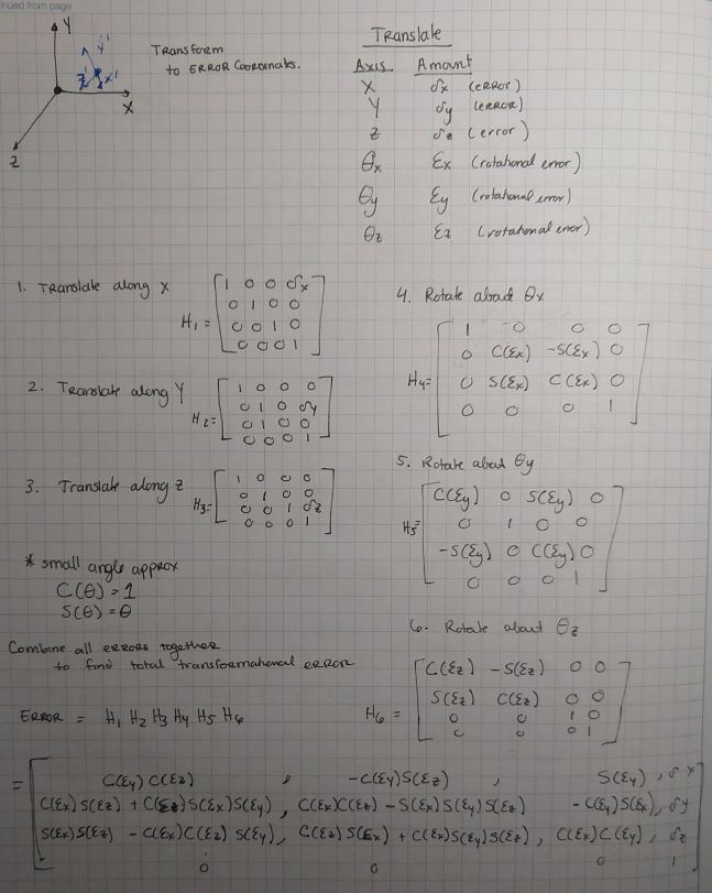
Handwritten derivation of the six elementary error transforms -- three translations along x, y and z, and three rotations about theta-x, theta-y and theta-z -- multiplied together into a single combined error matrix, with the small angle approximations cos theta equals 1 and sin theta equals theta noted alongside

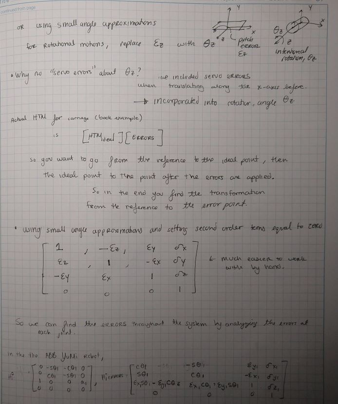
Continued notes: using small angle approximations for rotational motions, replacing epsilon-z with theta-z, a question about why there is no servo error about theta-z answered by noting it was already incorporated into the rotation angle, and the simplified error matrix with second-order terms set to zero -- annotated "much easier to work with by hand". Below, the ideal and error transforms written out for the ABB YuMi's first joint

Setting second-order terms to zero under the small-angle approximation gives a much more tractable error matrix — the one you can actually work with by hand.
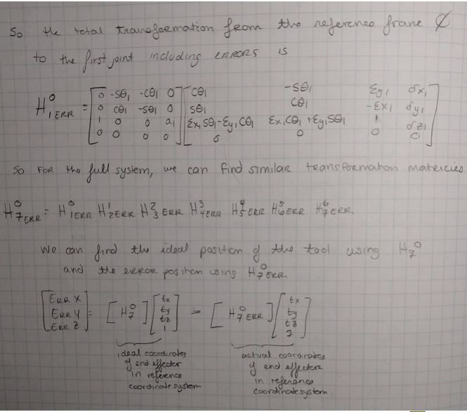
The total transformation from the reference frame to the first joint including errors, written as the product of the ideal transform and the error transform. Below, the full system as the product of all seven error-including transforms, and the comparison of the ideal tool position from H-0-7 against the actual position from H-0-7-ERR to give the error in x, y and z

Multiply the coordinate transformations by the error transformations in series and you get the actual end effector position relative to the reference frame. Difference that against the ideal position and you have the error in x, y and z.

The open question

Which leaves the part I don’t yet know: how do you predict the translational and rotational errors in the first place? I’ve seen a few examples online, and I’m looking forward to discussing it in class.

(If my interpretation of any of this is wrong, please tell me.)

References