RE-HOBI362 Rachel Hoffman-Bice, PhD
Seek & Geek

Seek & Geek 11: The Traffic Light, Continued

Four bolts, one 12 kN·m moment, and why they only need a tenth of their proof strength

Period Week 11

Picking up last week’s traffic light with the two things I left out: the weight of the beam itself, and the bolted connection that started the whole thing.
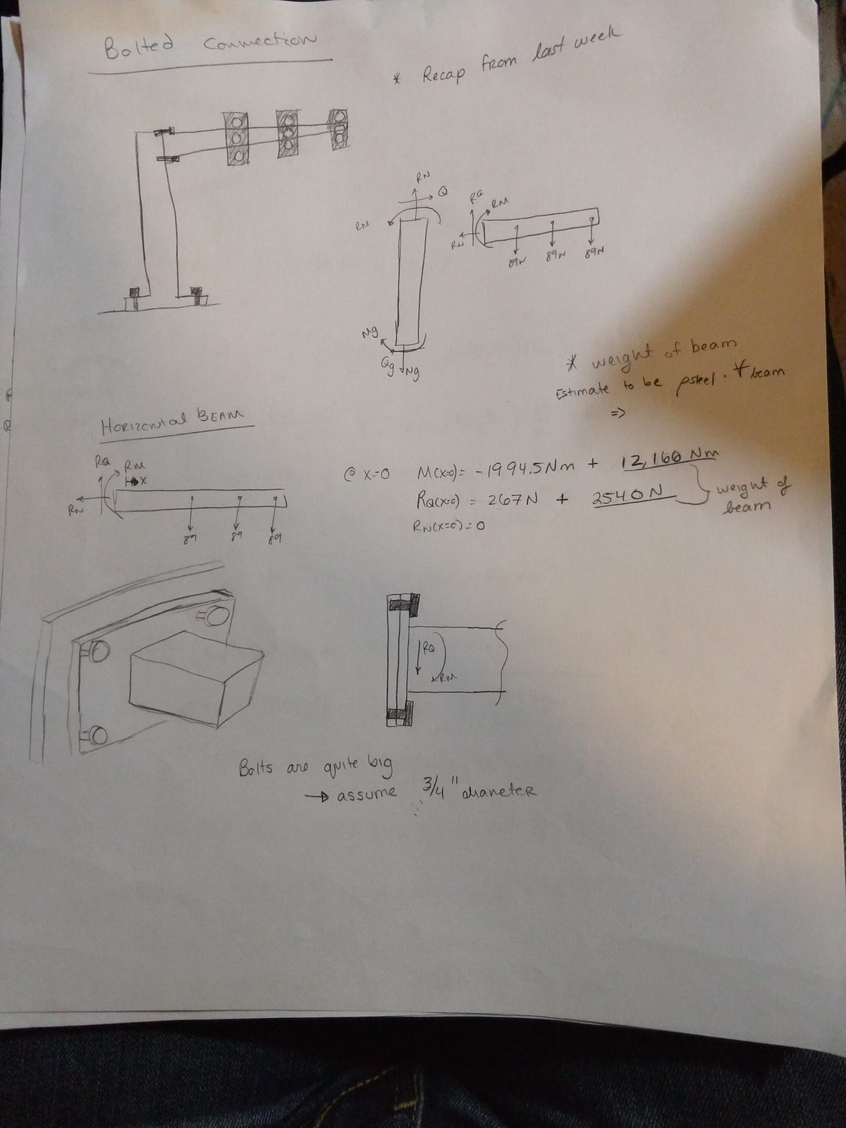
Notebook page headed "Bolted Connection", recapping last week's free body diagrams for the horizontal and vertical members and noting that the weight of the beam still needs estimating. Adding it changes the reaction moment from minus 1994.5 N·m to 12,166 N·m, with the beam weight of 2540 N bracketed as the new contribution. Sketches show the four-bolt flange pattern, and a note reads that the bolts are quite long, assume three-quarter inch diameter

The weight of the beam

The arm is a hollow tapered tube, so its mass needs an integral rather than a guess.
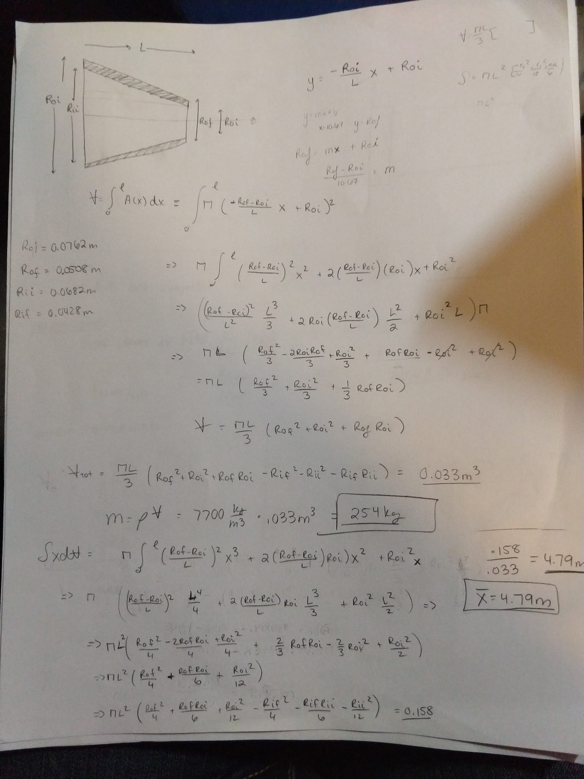
Notebook page integrating the tapered hollow section. The outer and inner radii are written as linear functions of position -- outer from 0.0762 m to 0.0508 m, inner from 0.0682 m to 0.0428 m -- and the cross-sectional area integrated along the length to give a total volume of 0.033 cubic metres. With steel at 7700 kg per cubic metre that is 254 kg. A first-moment integral divided by the volume puts the centroid at 4.79 m from the root

   
Beam mass 254 kg (2540 N)
Centroid 4.79 m from the root
Reaction moment, with beam weight 12,166 N·m

Adding the beam’s own weight multiplies the moment at the connection by roughly six. That is the load the four bolts actually have to carry.

What the bolts see
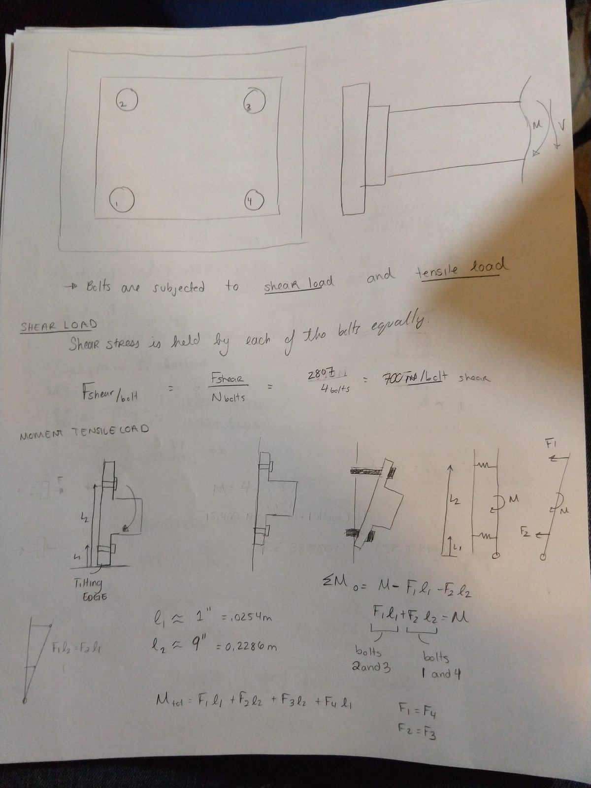
Notebook page splitting the bolt loading into two parts. Under shear load, the shear stress is held by each of the four bolts equally, giving 2807 N over 4 bolts, or 700 N per bolt in shear. Under moment tensile load, the flange is treated as tilting about its bottom edge, so bolt force is proportional to distance from that edge -- with lever arms of about 1 inch and 9 inches for the two bolt rows. Summing moments about the tilting edge relates the four bolt forces to the applied moment, with bolts 1 and 4 sharing one lever arm and bolts 2 and 3 the other

Two separate load paths:

  • Shear is carried equally: 2807 N ÷ 4 = 700 N per bolt
  • The moment is not. Treating the flange as tilting about its bottom edge, each bolt’s force is proportional to its distance from that edge, so the outer bolts do most of the work.
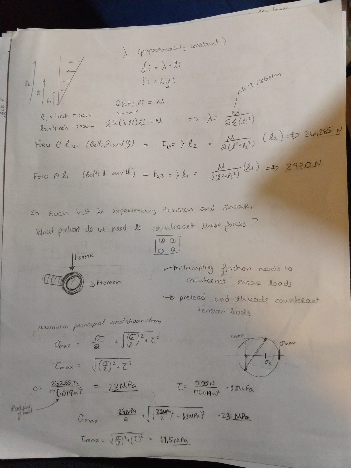
Notebook page solving the bolt forces. With a proportionality constant lambda relating force to lever arm, the moment sum gives lambda in terms of the applied moment and the two lever arms, resolving to 26,285 N in the far bolts and 2920 N in the near ones. Each bolt therefore sees both tension and shear, so the maximum principal and shear stresses are found with Mohr's circle -- a normal stress of 23 MPa and a shear stress of 0.5 MPa give a maximum principal stress of 23 MPa and a maximum shear stress of 11.5 MPa

   
Bolt force, far row 26,285 N
Bolt force, near row 2,920 N
Maximum principal stress 23 MPa
Maximum shear stress 11.5 MPa

Each bolt is in combined tension and shear, so the stresses come off Mohr’s circle rather than either load alone.

How much preload is needed?
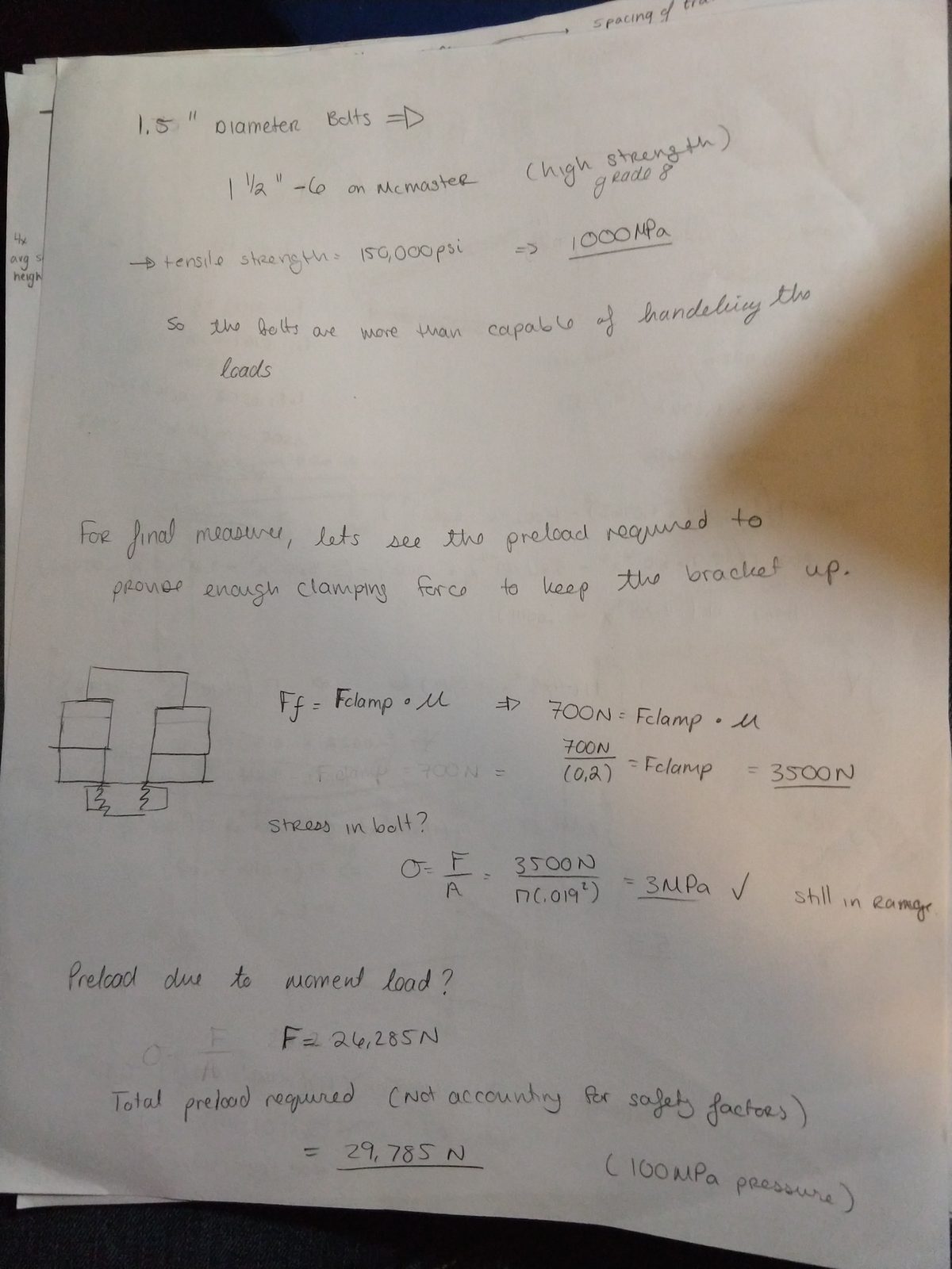
Notebook page checking bolt capacity and preload. 1.5 inch diameter grade 8 bolts from McMaster have a tensile strength of 150,000 psi, about 1000 MPa, so the bolts are more than capable of handling the loads. Then, for a final measure, the preload needed to provide enough clamping force to keep the bracket up: friction force equals clamping force times mu, so with 700 N of shear and a friction coefficient of 0.2 the clamping force needed is 3500 N, giving 3 MPa in the bolt, still in range. Adding the preload due to moment load of 26,285 N gives a total required preload of 29,785 N, or 160 MPa of pressure, not accounting for safety factors

The clamping force has to do two jobs: friction against the shear load, and preload against the tensile load from the moment.

   
Clamping force for friction (μ = 0.2) 3,500 N
Preload against the moment 26,285 N
Total preload required 29,785 N (160 MPa)
Bolt proof strength (1.5” grade 8) ~1000 MPa

The conclusion

So even with the required preload, the bolts are only experiencing about a tenth of their proof strength.

Bolts in permanent connections are typically preloaded to around 90% of proof strength, which would give this particular connection a safety factor of about 9. That doesn’t seem unreasonable, considering you’d want to replace these bolts perhaps once every 10–20 years rather than routinely.

There is still plenty more to consider when designing bolted joints — the stiffness of the joint and the fatigue life of the bolt among them — but those will have to wait.