RE-HOBI362 Rachel Hoffman-Bice, PhD
Seek & Geek

Seek & Geek 10: The Traffic Light

Shear, moment and tip deflection for a tapered mast arm — and a factor of safety of 13

Period Week 10

This week I walked to the Boston convention centre for the MedTech expo, and decided it would be fun to develop the free body diagrams for the unsung hero of the daily commute: the traffic light.

Two photographs of traffic signals in Boston: three signal heads hanging from a horizontal mast arm over an intersection with the city skyline behind, and a view looking up along the mast arm against a blue sky

What originally caught my attention was how the horizontal pole mounts to the vertical mast. You’d expect St. Venant to apply — that the horizontal pole would be embedded into the vertical mast by several diameters. But no. It appears to be just four bolts holding the connection.
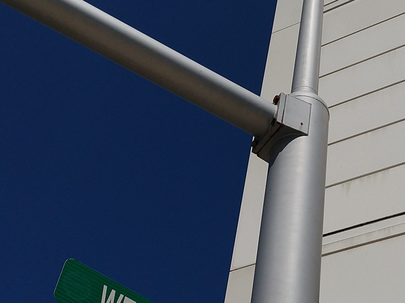
Close-up photograph of the joint where the horizontal mast arm meets the vertical pole, showing a small rectangular bracket and bolted flange rather than any deep embedment

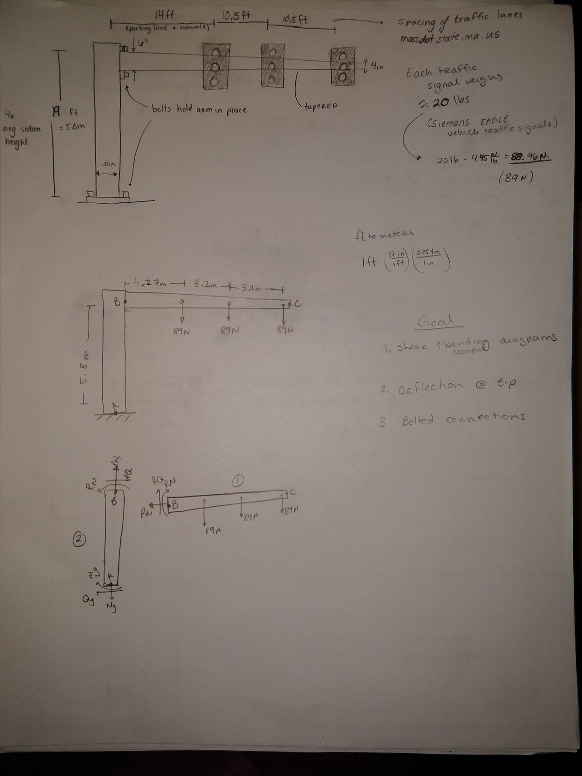
Setting up the problem

Notebook page setting up the traffic light. Dimensions come from MassDOT lane spacing: a 14 ft parking lane plus sidewalk and two 10.5 ft traffic lanes, with the mast 5.8 m tall at four times average sedan height. Each Siemens Eagle vehicle traffic signal weighs about 20 lb, converted to 89 N. The arm is noted as tapered, with bolts holding it in place. Three goals are listed: shear and bending moment diagrams, deflection at the tip, and bolted connections. Below, the beam is redrawn with the three 89 N loads at 4.27 m, 7.47 m and 10.67 m

Lane spacings came from MassDOT, and each Siemens Eagle signal head weighs about 20 lb — 89 N apiece, hung at 4.27 m, 7.47 m and 10.67 m along the arm.

Shear and moment
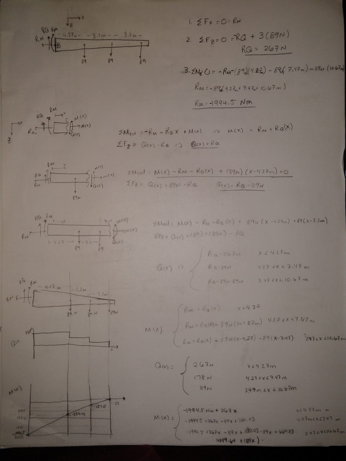
Notebook page working the statics. Summing forces and moments at the fixed end gives a reaction moment R-M of minus 1994.5 N·m and a shear reaction R-Q of 267 N. Cuts are then taken in each of the three spans to build piecewise expressions for the shear Q of x and moment M of x, and the resulting shear and bending moment diagrams are drawn beneath, the moment falling linearly from minus 1994.5 N·m at the wall to zero at the tip

   
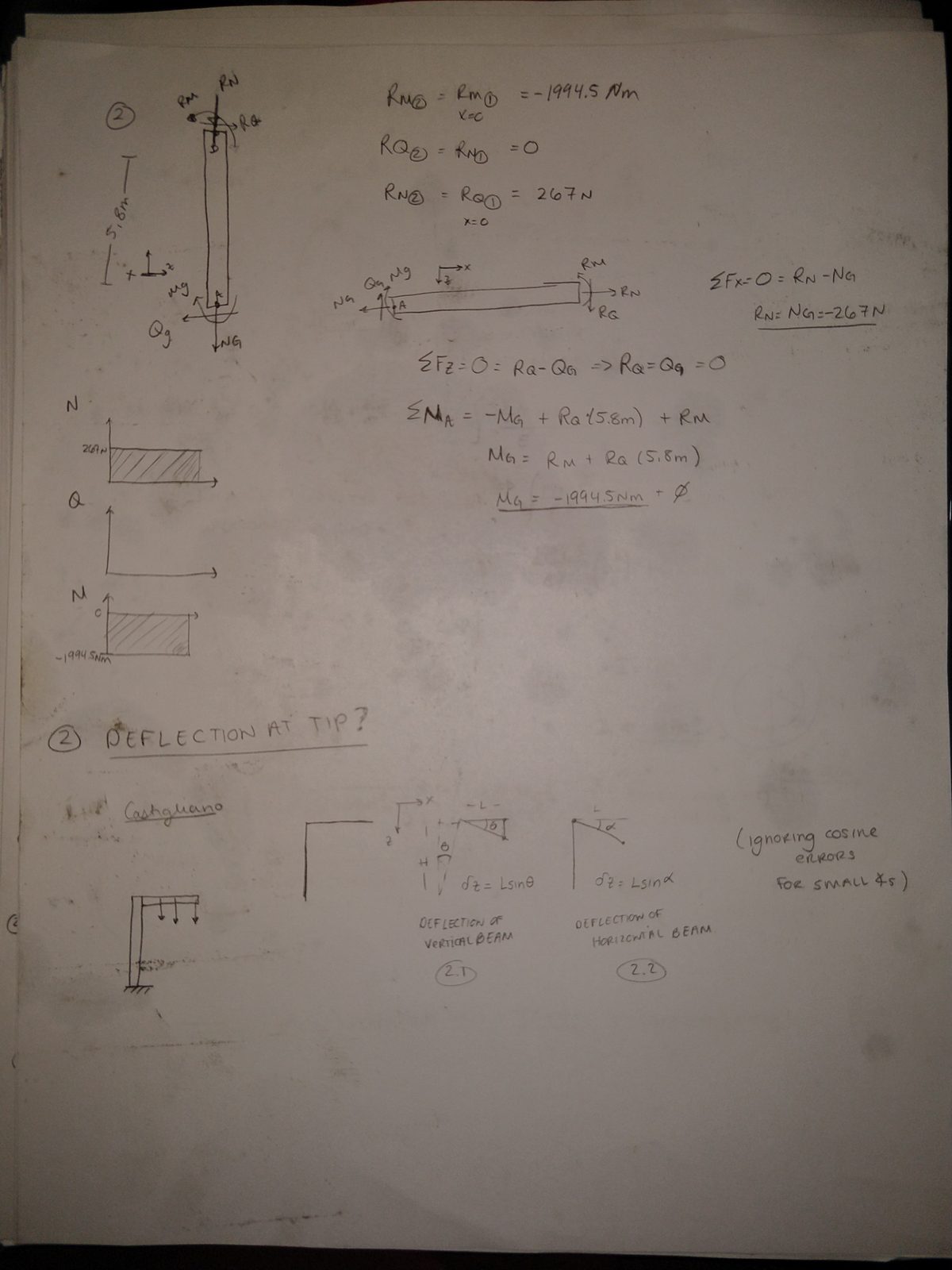
Reaction moment at the mast −1994.5 N·m
Reaction shear 267 N

Notebook page carrying the reactions through to the vertical mast, checking equilibrium at the base and confirming the moment carried down the pole, then setting up the two deflection contributions -- the deflection of the vertical beam and the deflection of the horizontal beam -- to be found by Castigliano's method

Deflection at the tip

The tip moves for two reasons: the mast itself bends, and the arm bends.
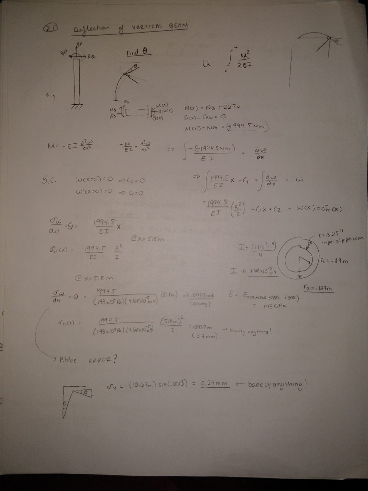
Notebook page finding the deflection of the vertical beam. Integrating the moment-curvature relation with fixed-end boundary conditions gives the slope at the top of the 5.8 m mast as 0.0013 rad, or 0.0745 degrees. With a 3.125 inch wall thickness from imperialpipe.com, an outer radius of 0.127 m and stainless steel at 193 GPa, the horizontal deflection is 3.7 mm. Carrying that slope out along the 10.67 m arm through Abbe error contributes 0.24 mm at the tip -- annotated "barely anything!"

The mast’s contribution turns out to be 0.24 mm at the tip — barely anything.
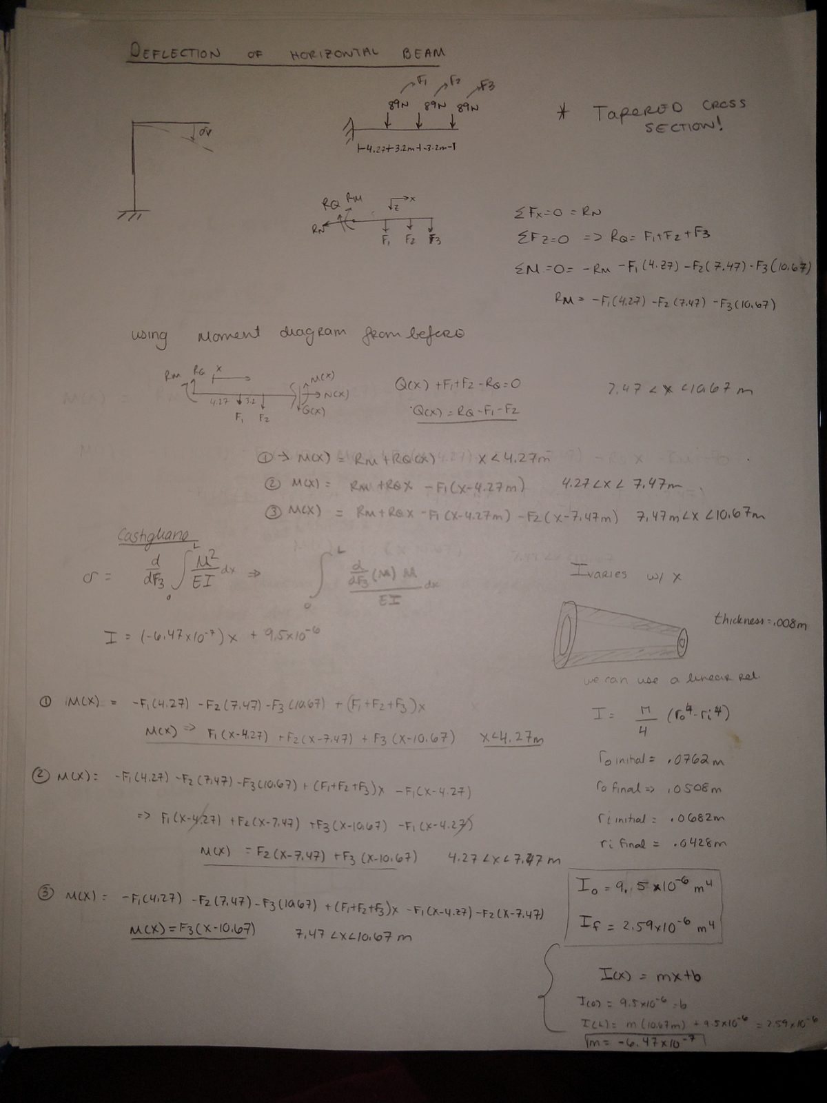
Notebook page setting up the horizontal beam, marked "tapered cross section!". Moment diagrams are written piecewise from the free end, and Castigliano's method is applied with a dummy load. Because the second moment of area varies along the beam, a linear relation is fitted for I of x between the initial and final radii, giving I-o of 9.5 by 10 to the minus 6 and I-f of 2.59 by 10 to the minus 6 metres to the fourth

The taper is the awkward part. Integrating the varying second moment of area properly didn’t seem like a good use of time, so I approximated the beam as three sections of constant cross-section.
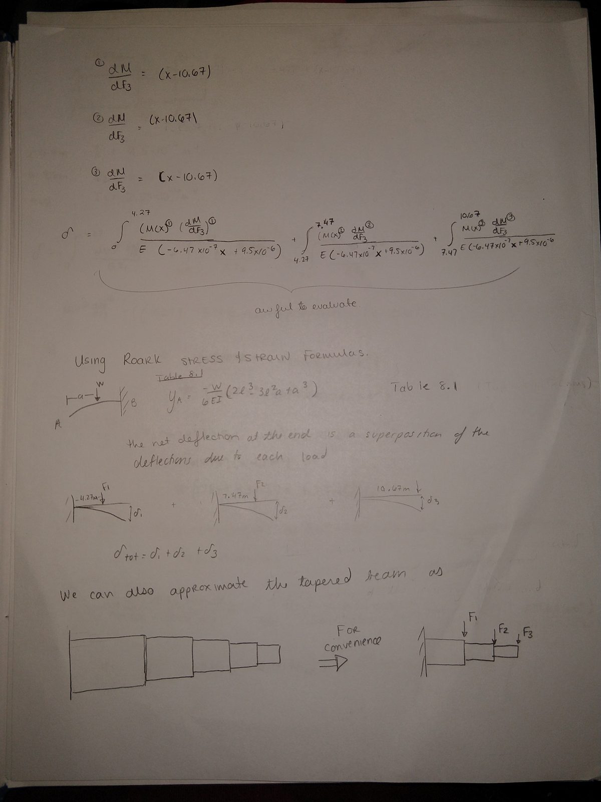
Notebook page continuing with Roark's stress and strain formulas, Table 8.1, noting that the net deflection at the end is a superposition of the deflections due to each load, and sketching the tapered beam approximated as five stepped constant sections for convenience

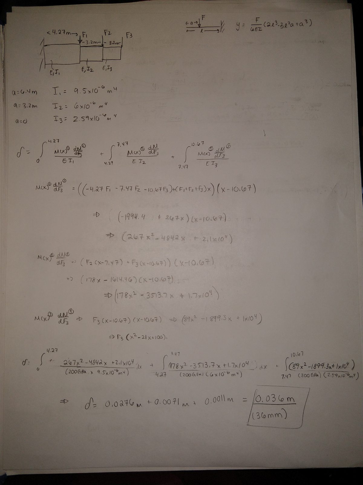
Notebook page evaluating the superposed integrals over the three constant-I segments, with I-1 of 9.5 by 10 to the minus 6, I-2 of 6 by 10 to the minus 6 and I-3 of 2.59 by 10 to the minus 6 metres to the fourth, summing three contributions of 0.0276 m, 0.0071 m and 0.0011 m to a boxed total of 0.036 m or 36 mm

Tip deflection: 36 mm.

How does the taper affect stress?
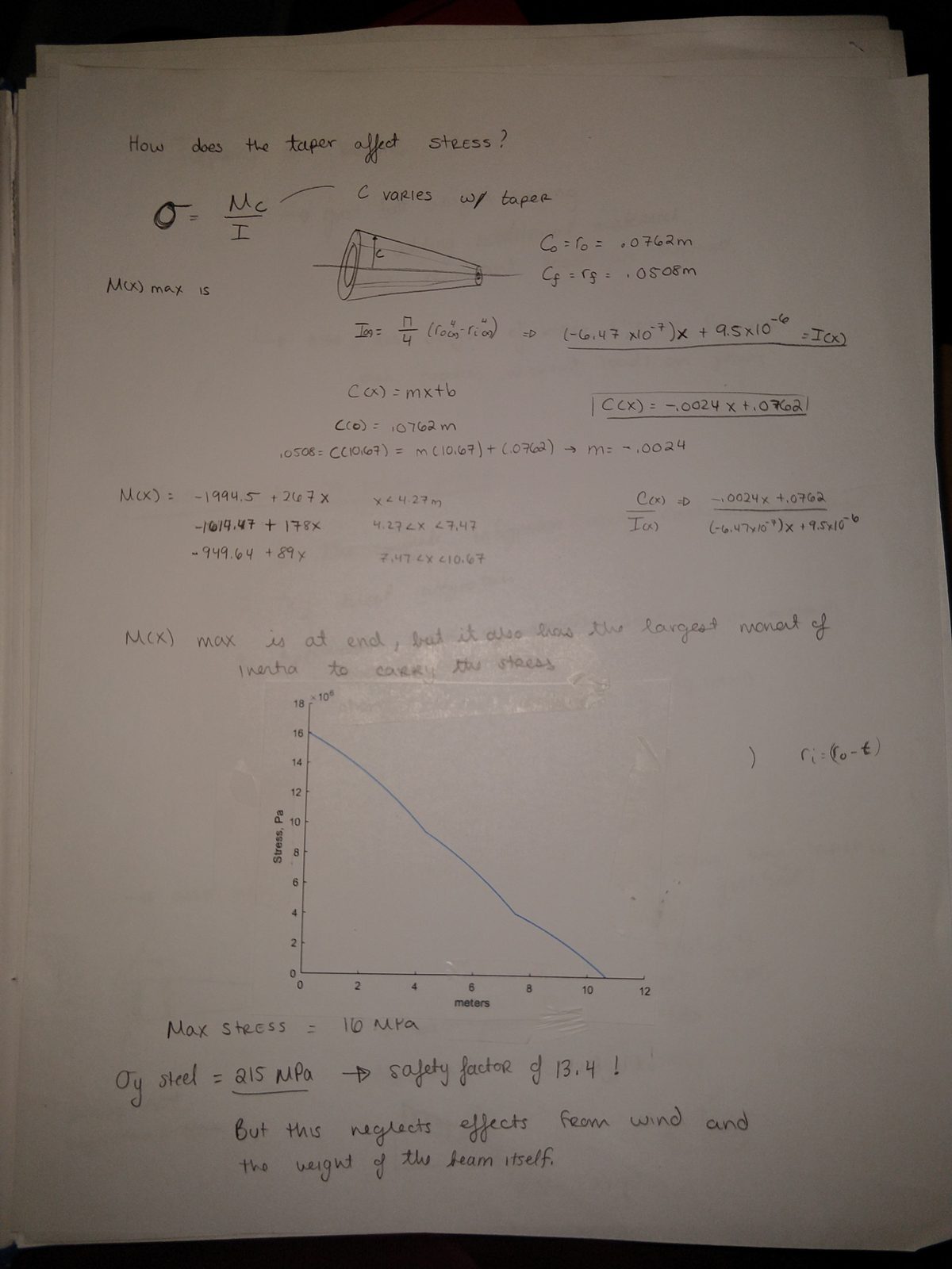
Notebook page asking how the taper affects stress, since in sigma equals M c over I the distance c to the outer fibre varies along the beam too. A linear expression for c of x is fitted between the 0.0762 m root and 0.0508 m tip radii, and the ratio c over I is formed. A MATLAB plot of stress in Pa against position in metres shows stress rising from zero at the tip to about 16 by 10 to the 6 Pa at the root. Maximum stress is 16 MPa against a steel yield of 215 MPa, giving a safety factor of 13.4, with the note that this neglects wind and the weight of the beam itself

The taper matters twice over: the maximum moment is at the root, but so is the largest second moment of area to carry it.

   
Maximum stress 16 MPa
Steel yield 215 MPa
Factor of safety 13.4

What’s missing

One thing I left out is the weight of the horizontal beam itself — which is one of the main reasons the beam is tapered in the first place. That load, plus wind, rain and snow, would bring the factor of safety down to perhaps 3–5. I say that because a factor of 10 is quite large, and would suggest an over-engineered system.

There’s also a real chance my values for diameter, wall thickness and material are off. I did my best to find comparable specifications online, but those assumptions matter — the wall thickness is essentially squared when computing the beam’s second moment of area.

Continued in Seek & Geek 11, which takes on the bolted connection and the weight of the beam.