RE-HOBI362 Rachel Hoffman-Bice, PhD
Seek & Geek

Seek & Geek 9: Planetary Gearboxes

Deriving the transmission ratios from scratch, then finding which component actually limits torque

Period Week 9

This week I found a really cool planetary gearbox in a bin in my lab. I’ve always wanted to work through the derivation of the transmission ratios for planetary systems properly, so this seemed like the chance.
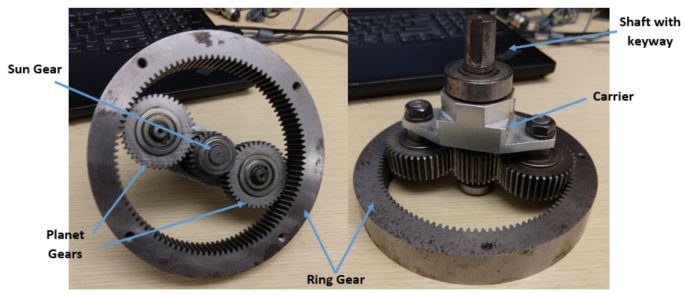
The planetary gearbox in two photographs, annotated with the sun gear, three planet gears and the ring gear on the left, and on the right the carrier and the output shaft with keyway

One of the genuinely interesting things about planetary gear sets is that you get several different transmission ratios out of the same hardware depending on which member you hold fixed and which you drive. The typical configuration fixes the ring and drives the sun, with a shaft on the carrier as the output.

Why the usual formula never satisfied me

For an ordinary gear transmission the ratio comes straight from the sizes of the gears, and the same relations hold between torque and rotational velocity.
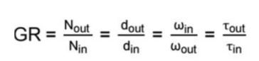
The gear ratio definition: GR equals N out over N in, equals d out over d in, equals omega in over omega out, equals tau out over tau in

That applies to planetary boxes too — but with one member stationary the overall ratio gets harder to see, and I was never satisfied just using the formulas some textbooks and websites hand you. So I derived them.
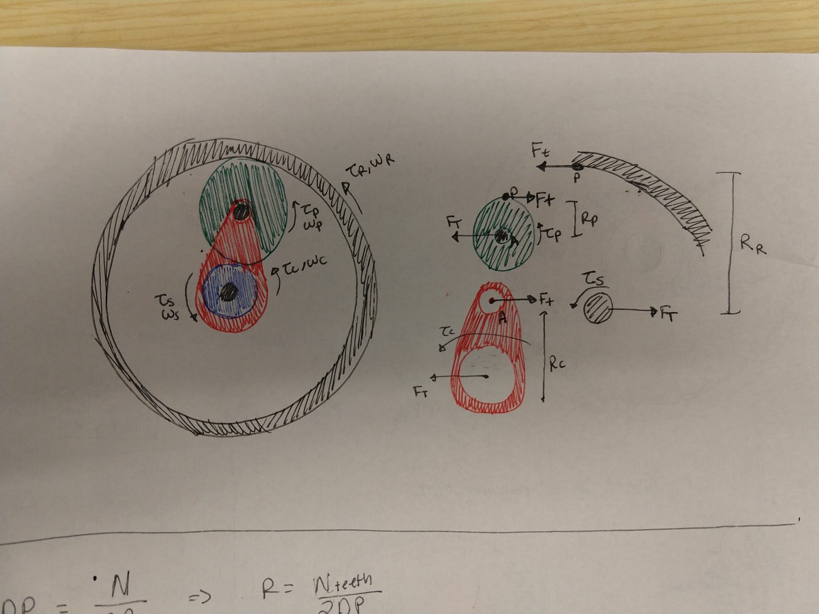
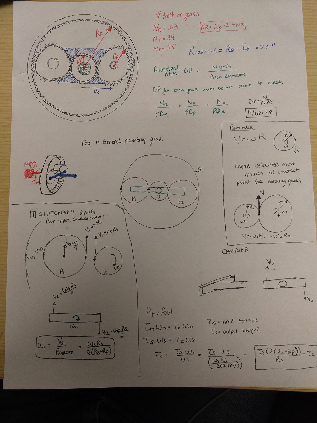
Hand-drawn free body diagrams of the gearbox. On the left, the assembled set in colour with the sun, a planet and the carrier arm labelled with their torques and angular velocities. On the right, the members separated out with the tangential force F-t acting at each mesh, and the ring, planet and carrier radii marked

Setting up the geometry

Notebook page recording the tooth counts -- ring 103, planet 39, sun 25 -- and the boxed relation N-R equals 2 N-P plus N-S, with the carrier radius as R-S plus R-P equal to 2.5 inches. Diametral pitch is defined as teeth over pitch diameter, noted as needing to be the same on every gear for them to mesh. A reminder box records that linear velocities must match at the contact point of meshing gears, V equals omega R. Below, the carrier is analysed and the stationary-ring case worked, giving omega-C equals omega-S R-S over 2 times the quantity R-S plus R-P

   
Ring teeth 103
Planet teeth 39
Sun teeth 25

The constraint N_R = 2·N_P + N_S has to hold for the set to assemble, and it does: 2(39) + 25 = 103.

The key physical fact everything rests on is that linear velocities must match at the contact point of meshing gears — V = ωR. From there each configuration is just bookkeeping.
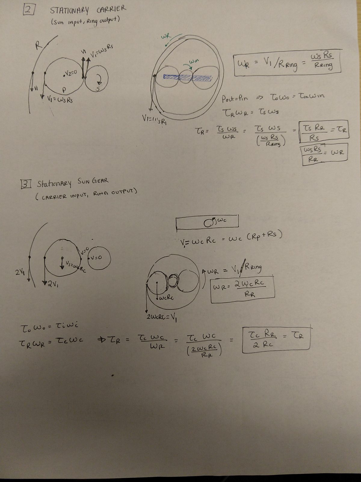
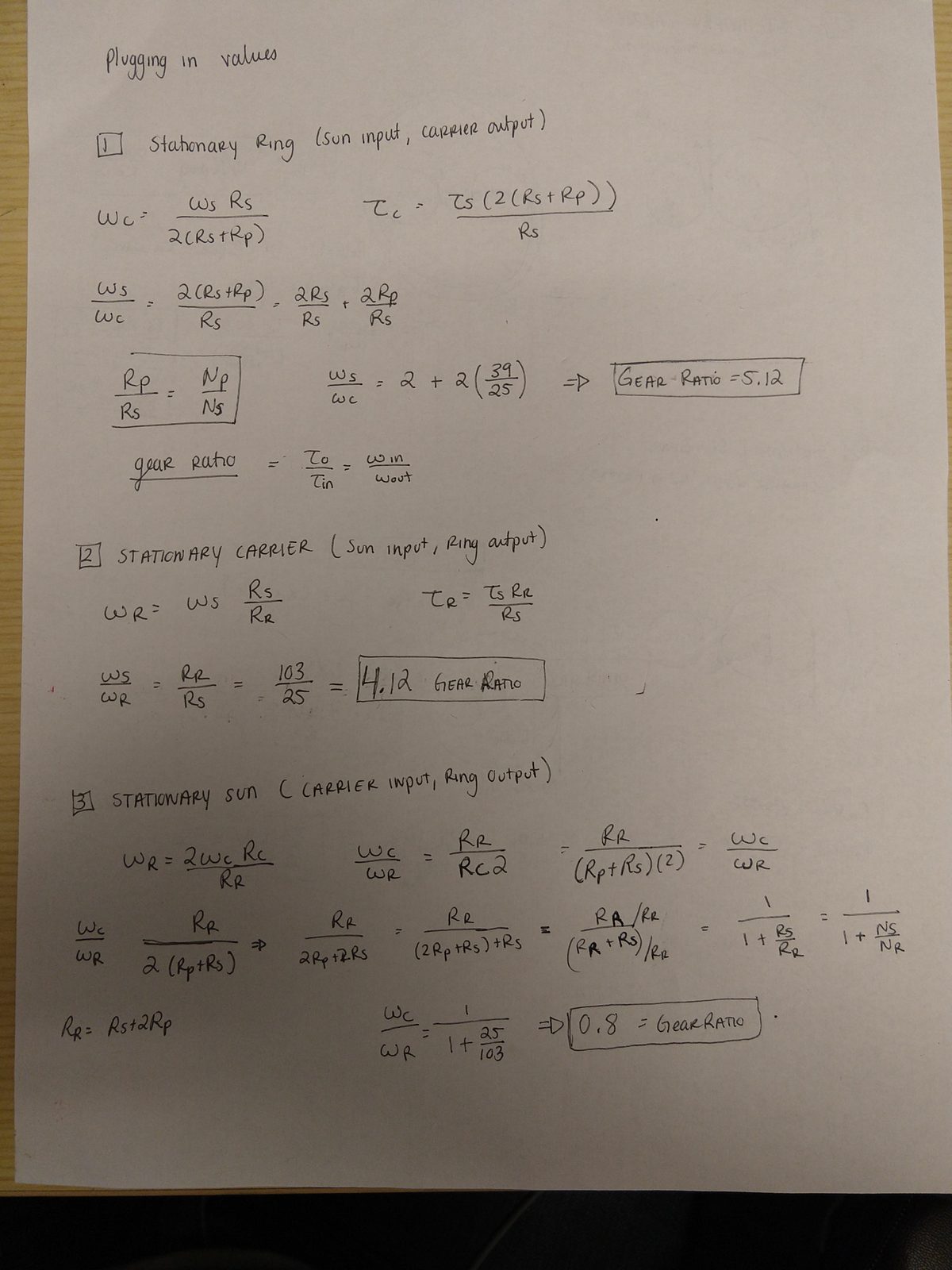
Notebook page working the second and third configurations. Case 2, stationary carrier with sun input and ring output, tracks the velocity at each mesh point to relate omega-R to omega-S, then uses power in equals power out to get the torque ratio. Case 3, stationary sun with carrier input and ring output, does the same

Three ratios from one gearbox

Notebook page substituting the actual tooth counts into all three derived expressions. Stationary ring with sun input and carrier output gives a gear ratio of 5.12. Stationary carrier with sun input and ring output gives 4.12. Stationary sun with carrier input and ring output gives 0.8

Held fixed Input → Output Ratio
Ring Sun → Carrier 5.12
Carrier Sun → Ring 4.12
Sun Carrier → Ring 0.80

Same three gears, three quite different machines.

What actually limits the torque?
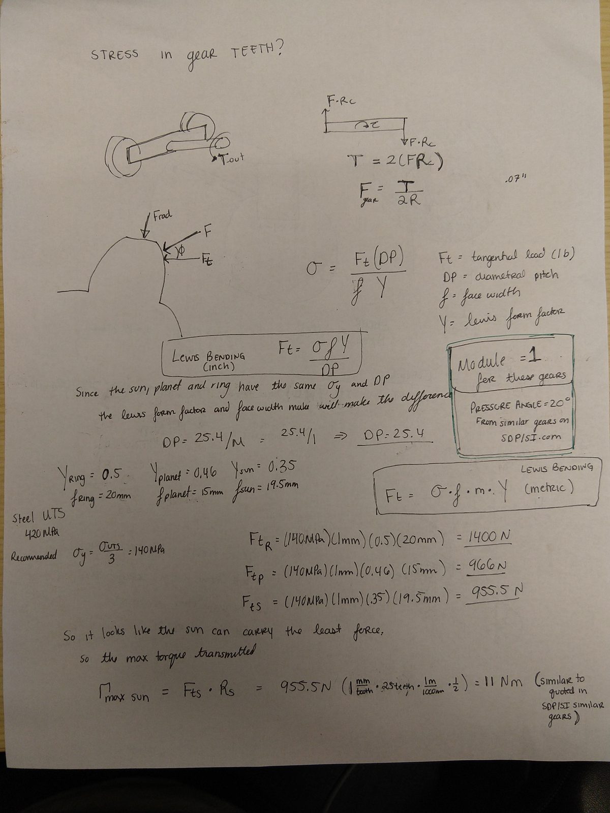
Notebook page analysing tooth stress. The Lewis bending equation is set up with tangential load, diametral pitch, face width and the Lewis form factor. Since the sun, planet and ring share the same yield stress and diametral pitch, the form factor and face width decide which is weakest -- form factors of 0.5, 0.46 and 0.35 and face widths of 20, 15 and 19.5 mm for ring, planet and sun. Working each gives allowable tangential loads of 1400 N, 966 N and 955.5 N, so the sun carries the least force, and the maximum sun torque works out to 11 N·m

Since the sun, planet and ring share the same material and diametral pitch, the Lewis form factor and the face width are what decide which one gives first.

Gear Allowable tangential load
Ring 1400 N
Planet 966 N
Sun 955.5 N

The sun gear teeth are the limiting factor — maximum input torque of about 11 N·m. But thanks to the ratios derived above, that becomes roughly five times as much torque at the carrier output with the ring held stationary.

Checking the other failure paths
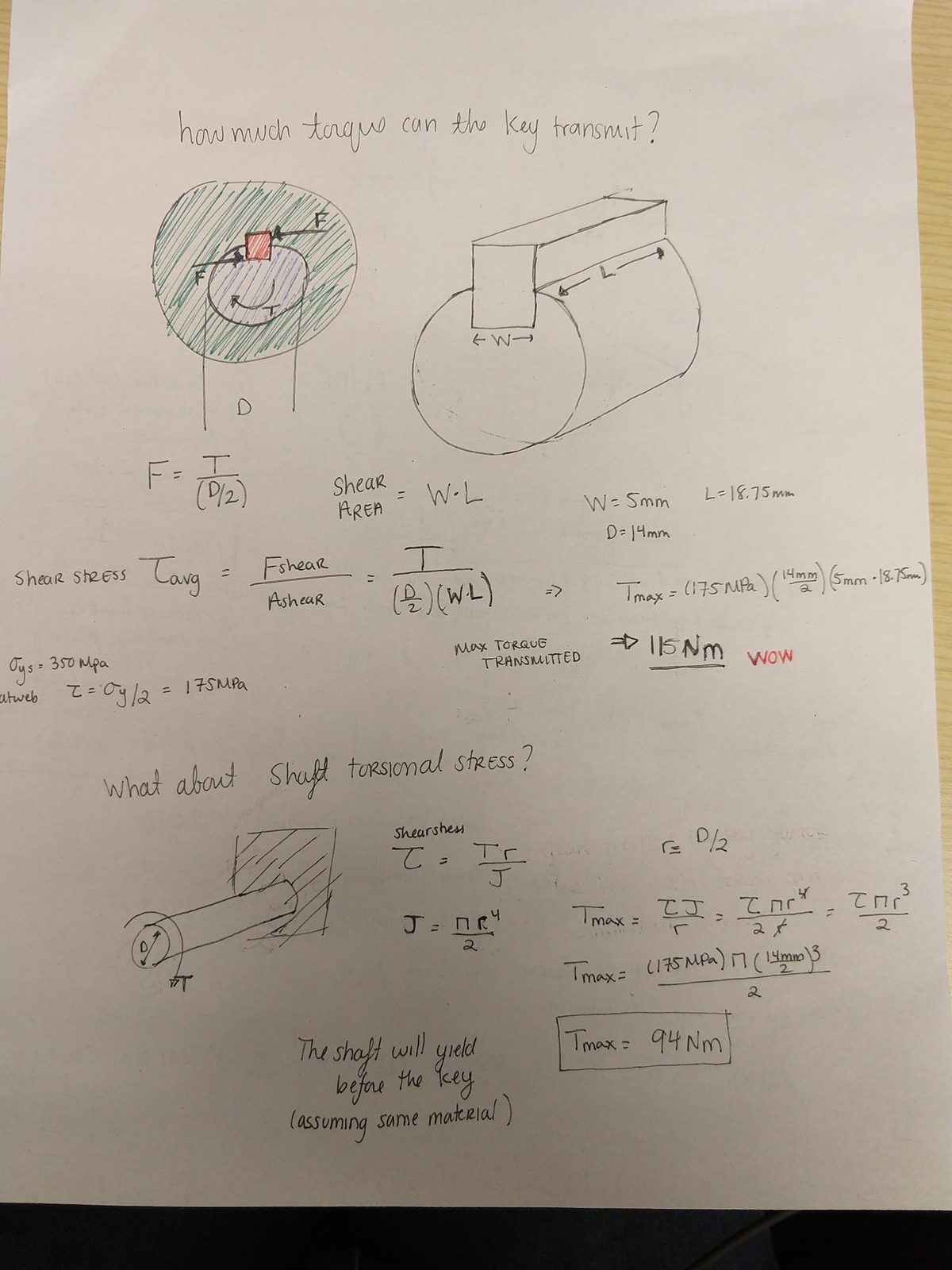
Notebook page checking the key and shaft. The key is analysed in shear with a 5 mm width, 14 mm shaft diameter and 18.75 mm length, giving a maximum transmitted torque of 115 N·m, annotated "WOW" in red. The shaft is then checked in torsion with the polar moment of inertia, giving a maximum of 94 N·m, with the conclusion that the shaft will yield before the key assuming the same material

   
Key in shear 115 N·m
Shaft in torsion 94 N·m
Sun gear teeth 11 N·m

So the ordering is clear: the teeth give out roughly an order of magnitude before either the key or the shaft. Between those two, the shaft would yield before the key, assuming the same material.

Reference