In heavy industry, parts like ship-engine cylinder cases and wind-turbine gearbox shafts weigh tens to hundreds of kilograms, and they still have to be lowered into holes with very little clearance. Today that is done with an overhead crane and skilled workers who push and pull the hanging part into line while someone else runs the hoist. Those workers are getting harder to find, and a mistake can damage expensive parts.
My PhD, “Precision Assembly of Underconstrained Heavy Shafts Suspended By Multiple Cables From A Robotic Crane,” asks whether the crane can do that fine work itself. Instead of making the crane more precise, I made the way the load hangs do the work: a heavy shaft suspended from several cables, attached at the right positions and angles, can be inserted into a chamfered hole with 120 µm of clearance even though the crane can’t place it that accurately.
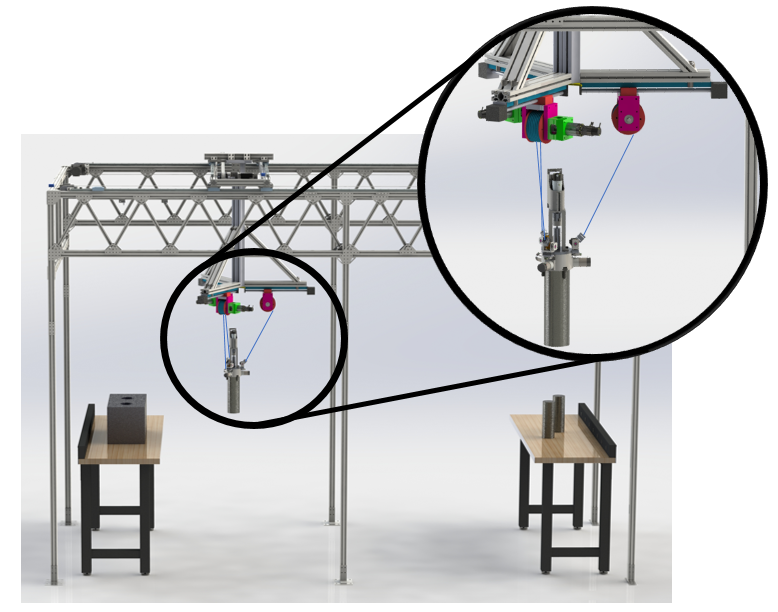
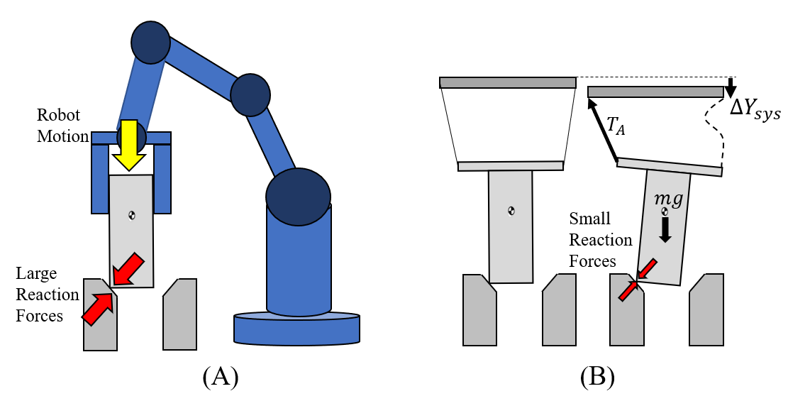
A large industrial robot can do peg-in-hole assembly, but it controls every degree of freedom of the part, needs precise force control to do it safely, and takes up a large, permanent footprint on the factory floor. Cable-driven parallel robots handle heavy loads well, but they have the same fixed footprint.
I took a different route: mount the winches of a cable-suspended robot on a platform that hangs from the factory’s existing gantry crane. The crane does the coarse motion and the winches do the fine motion, with no footprint of its own. The system is deliberately underactuated, and that turns out to be an advantage. Cables can only pull. If the peg lands badly on the chamfer, one cable simply goes slack instead of driving the peg harder into the hole, so the only force on the part is its own weight. A stiff robot in the same situation can push hard enough to damage both parts.
The WinchBot in action
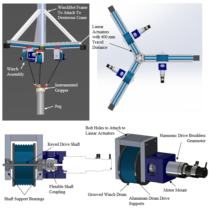
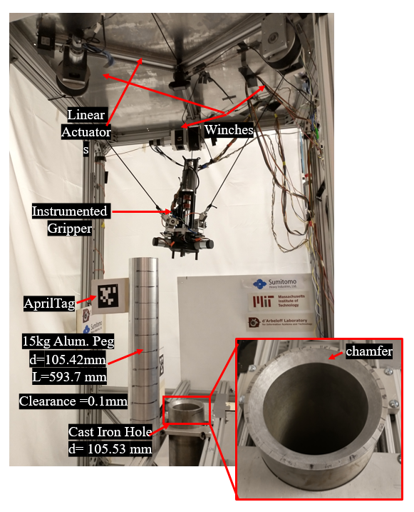
The WinchBot prototype
I designed and built the WinchBot, a scaled three-winch prototype. Each winch sits on its own linear actuator with 400 mm of travel, spaced 120° apart, and each drives a single cable down to an instrumented gripper holding the peg. The winches use Harmonic Drive brushless gearmotors with ODrive controllers, absolute encoders, and load cells read through HX711 amplifiers for real-time tension, all wired through Arduino on protoboard I soldered myself and controlled in Python. The winch drums and housings were 3D-printed on a Markforged composite printer.
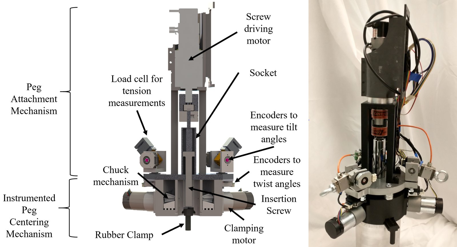
The gripper does the sensing. An IMU measures the peg’s tilt, encoders measure the cable attachment and twist angles, load cells measure tension, and motorized chuck and clamping mechanisms grip and center the peg.
I also used computer vision to watch what the peg was actually doing. I tracked two fiducial tags with a camera: one attached to the peg to track its position and orientation, and one attached to the hole as ground truth. On the 2D rig I used ArUco tags with OpenCV, and on the 3D WinchBot I used AprilTags. Comparing the peg tag’s motion to what the winches were doing showed whether the peg was being inserted properly or had become jammed or wedged.
The test peg is aluminium, 15 kg, 105.42 mm in diameter and 593.7 mm long. The matching cast-iron hole is 105.53 mm, which leaves 120 µm of clearance, with a static coefficient of friction of 0.67 between them.
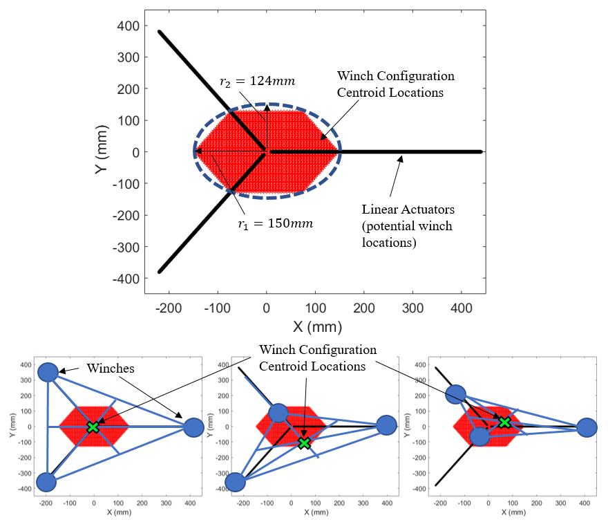
Using the linear actuators, the winches can also be repositioned. By solving the inverse kinematics as an optimization, with the peg position known and the tilt and cable tensions unknown, over thousands of candidate winch placements, I can pick the configuration that places the peg with the least tilt before insertion starts.
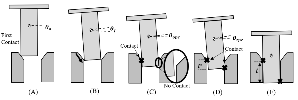
Stages of insertion
Getting a cable-suspended peg all the way in means getting through five stages: first contact with the chamfer, crossing the chamfer, one-point contact, two-point contact, and full insertion. Each stage fails in its own way. I worked out the first stages in 2D, with the peg hanging from two cables, and then took jamming and wedging into 3D on the WinchBot.
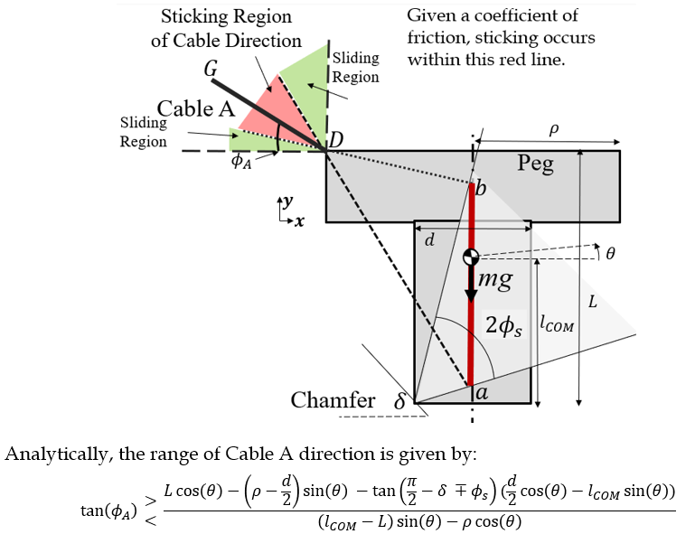
Crossing the chamfer: the sticking region
When the peg first touches the chamfer, the point in contact can only do one of three things: move up the chamfer, stay where it is, or slide down toward the center of the hole. Because the cables can only pull, the peg is being lowered and its weight pulls it down, moving up the chamfer is physically impossible. That leaves two outcomes. If the contact point stays put, the peg rotates about it, one cable goes slack, and the chamfer crossing fails. If it slides down, both cables stay taut and the peg moves toward the hole.
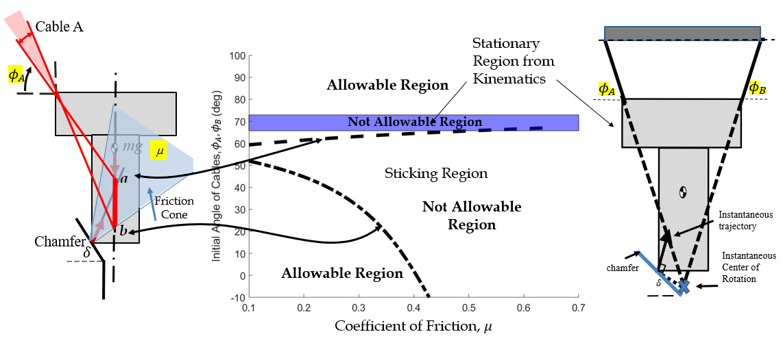
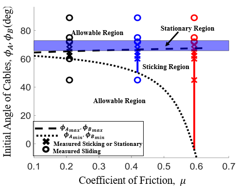
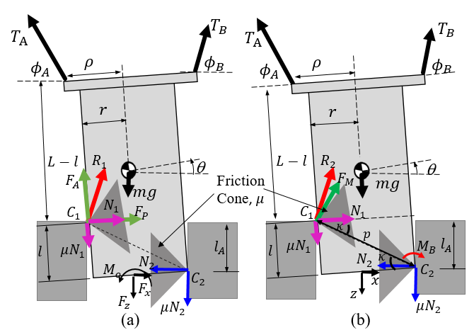
I looked at the conditions for each outcome in two ways, a force balance and the kinematics. For the force balance: if the peg’s weight, the tension in one cable and the chamfer’s reaction force all meet at a single point, the peg sticks and the other cable goes slack. The friction cone limits where those three forces can meet to a line segment on the peg, so I can find the cable directions that miss that segment entirely. That gives an analytic range of cable angles, in terms of the peg geometry and the coefficient of friction, for which sticking can’t happen. Short pegs need large cable angles to avoid it, and long pegs need small ones.
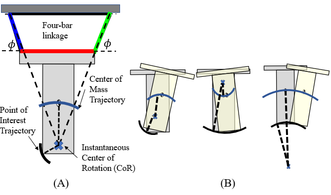
For the kinematics: while both cables are taut they act as rigid links, and together with the peg and the base they form a four-bar linkage. The linkage’s instantaneous center of rotation sets the path the contact point wants to follow. I simulate the chamfer crossing by lowering the system a fraction of a millimeter at a time and finding where that path meets the chamfer surface. Where the path would take the peg up the chamfer, the cables can’t push, so the peg stays stationary and tips over instead. That gives a second, kinematic region of cable angles to avoid.
Together the sticking region and the stationary region mark out which combinations of cable angle and friction are allowable.
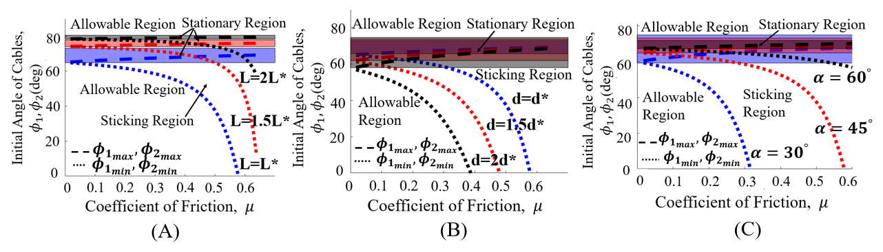
How big those regions are depends on the peg and hole. As the peg gets longer, the not-allowable region shrinks until only very steep cable angles are ruled out. As the peg gets wider, it grows, and for wide pegs with high friction a successful chamfer crossing becomes nearly impossible. A steeper chamfer shrinks it, since the chamfer itself guides the peg toward the center of the hole.
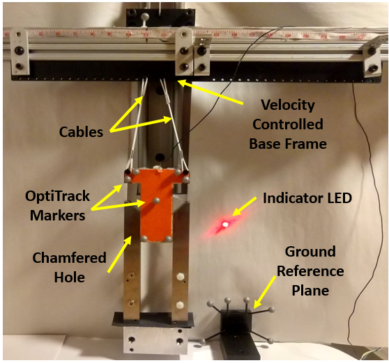
The 2D experimental setup
To test the theory, I built a 2D experimental setup: a velocity-controlled base frame carrying two cables that hold a peg over a chamfered hole. I tracked the peg and the hole with OptiTrack motion capture, and an indicator LED signals when the peg makes contact.
2D experimental results
First, I varied the coefficient of friction between the peg and the hole using different types of tape, and attempted insertion across a range of cable angles. Every trial where the peg stuck or stayed stationary on the chamfer (marked ×) fell inside the predicted not-allowable region, and every trial where it slid down the chamfer (marked ○) fell outside it.
The 2D rig at three cable angles. At 41° and 84° the peg slides down the chamfer and reaches two-point contact, lighting the indicator LED. At 67°, inside the not-allowable region, cable B goes slack and the chamfer crossing fails.
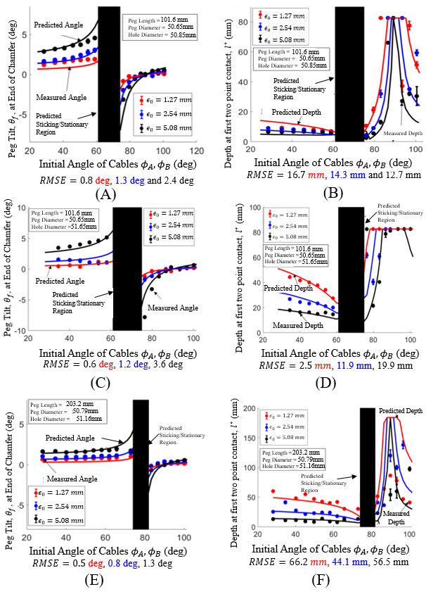
Next, I checked the chamfer-crossing simulation against the experiment. Across different peg lengths, clearances and starting offsets, averaging five trials at each cable angle, the measured peg tilt at the end of the chamfer tracked the predicted tilt with a root-mean-square error of 0.5° to 3.6°.
The demonstration video accompanying the IROS 2020 paper.
Passive sway control
The cable angles also set how the peg sways while the crane carries it. That matters on a factory floor, where you don’t want a heavy shaft swinging around, and at the hole, where you don’t want it bouncing off the chamfer on first contact. With very large cable angles the peg sways slowly with very little damping, so it swings for a long time. With small angles it sways quickly and settles fast. And at a sweet spot in between, the sway cancels almost immediately and the peg resists outside disturbances.
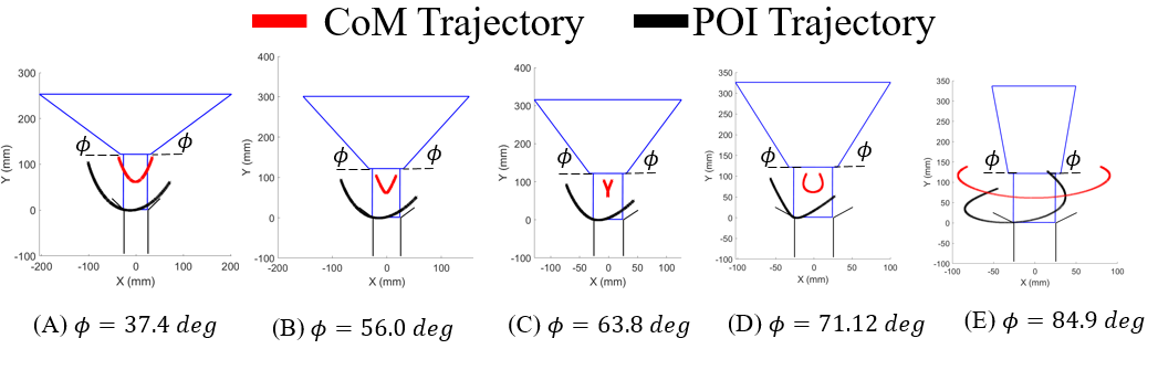
Predicting the depth of insertion
The last thing the cable angles decide is how deep the peg is when two-point contact begins. That depth matters because a shallow two-point contact is where wedging happens. Using the same four-bar simulation, I predict that depth from the cable angle, and the 2D experiments followed the predictions across peg lengths, clearances and starting offsets. The largest errors came at very large cable angles, above about 85°, where the depth is especially sensitive.
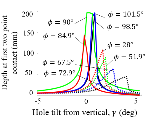
A hole that isn’t perfectly vertical changes the answer. If the hole is tilted in line with the peg’s path, two-point contact starts deeper. If it’s tilted the other way, it starts shallower. Pegs hung at large cable angles are the most sensitive to hole tilt.
Choosing the cable hanging angles
All of that adds up to a design sequence for hanging any peg:
- Define the peg and hole geometry.
- Find the sticking and stationary regions, and rule out the cable angles inside them.
- For the allowable angles, simulate the chamfer crossing and rule out any angle that leaves the peg too tilted to enter the hole.
- For the angles that remain, simulate one-point contact and choose the one with the deepest two-point contact.
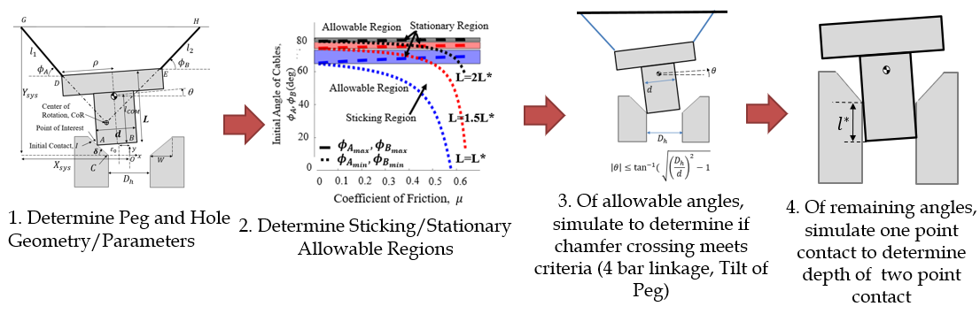
This work was published in IEEE Robotics and Automation Letters and presented at IROS 2020.
Jamming and wedging
Once the peg is in two-point contact, touching the hole wall at two points, it can still fail in two ways. I took both into 3D on the WinchBot.
Jamming happens when the forces pushing the peg in are pointed the wrong way: they press the peg against the sides of the hole, and friction at the two contact points holds it there. The peg only moves again if the applied forces change. I derived the jamming condition for a peg hanging from three cables in 3D. The catch is that the condition depends on the angle of the plane through the two contact points, which you can’t measure while the peg is moving. So the control has to work for any contact angle, and that means driving six tension terms to zero at once. Balancing the vertical tension components and balancing the in-plane components turn out to be conflicting conditions, so you have to choose between them based on the peg geometry and cable angles. For a long peg on shallow-to-moderate cable angles, balancing the in-plane components wins, and that became my jam-free insertion controller.
Wedging happens when two-point contact starts too shallow. The contact forces point straight at each other inside their friction cones, the insertion force stores energy in the elastic deformation of the parts, and when that force is released the stored energy keeps the peg locked in place. Changing the insertion force won’t free it. The only real fix is to back the peg out and try again with less tilt.
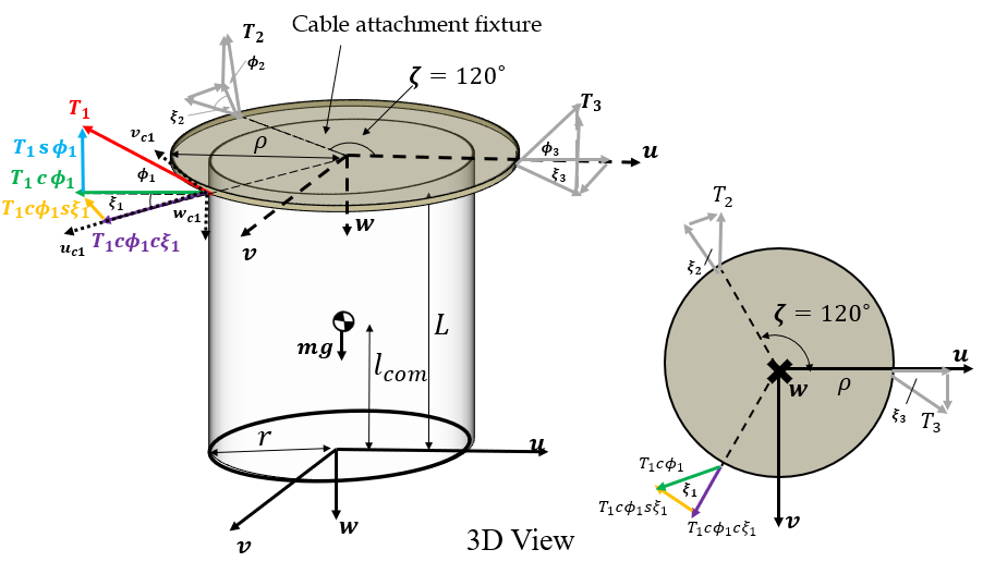
The WinchBot corrects a wedge on its own:
- Detect the wedge: all three cables go slack at once.
- Take up the slack, tightening each cable back to about its tension before the wedge.
- Break the wedge with a coordinated set of cable tensions. There are two strategies, and which works better depends on whether the cable angles are steep or shallow.
- Confirm it broke from a spike in peg acceleration and cable tension.
- Correct the tilt using the gripper’s IMU and coordinated cable lengths.
- Reinsert with the jam-free controller, repeating if needed.
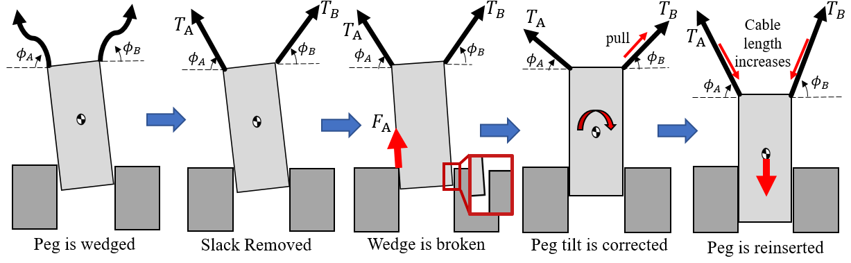
Jamming and wedging experiments
All three experiments below ran on the WinchBot with the winches in an equilateral configuration. Each plot is from the run shown in the video next to it.
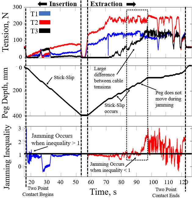
Without a controller. The peg is inserted and extracted with no control of the cable tensions. The three tensions drift far apart, the peg stick-slips on the way in, and on the way out it stops moving entirely: it has jammed. The jamming inequality leaves its safe range during both insertion and extraction, and you can hear the cables jitter and the peg rattle in the hole.
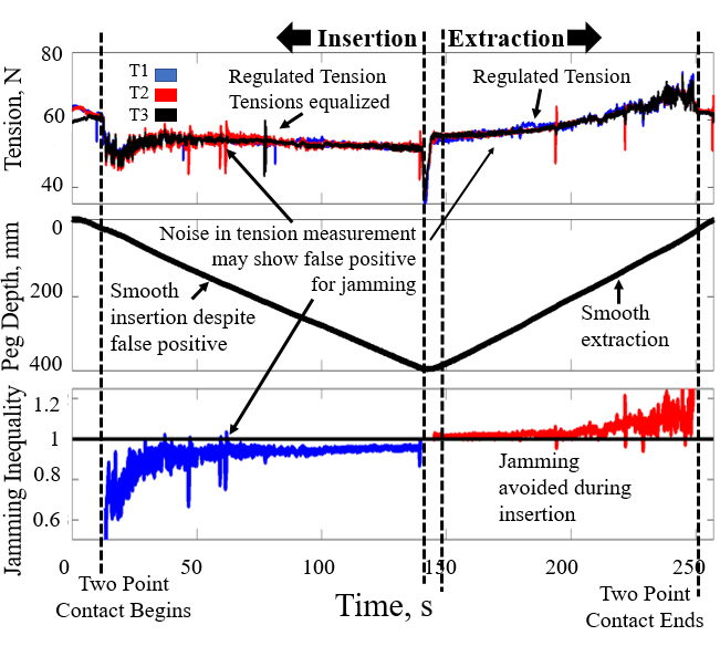
With the jam-free controller. Balancing the in-plane tension components keeps the three tensions nearly equal. Insertion and extraction are both smooth, and the jamming inequality stays satisfied the whole way. A few noisy tension readings briefly look like jamming, but the peg depth shows it never stopped.
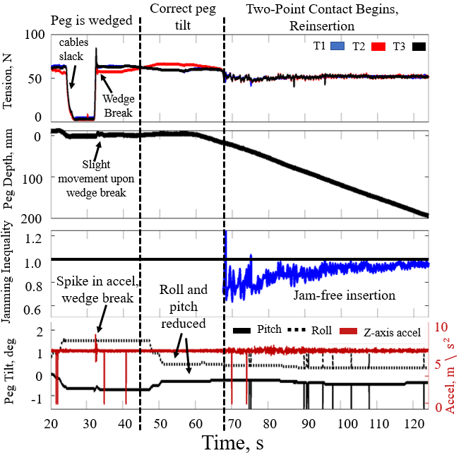
Wedge correction. When the peg wedges, all three cable tensions drop to zero at once. The WinchBot takes up the slack and breaks the wedge, which shows up as a spike in tension and in the peg’s vertical acceleration, with only a slight movement in depth. It then reduces the peg’s roll and pitch and reinserts it with the jam-free controller, and the peg goes in smoothly.
The jamming and wedging work was published in IEEE Robotics and Automation Letters and presented at IROS 2021.
Where it landed
The WinchBot inserts a 15 kg peg into a hole with 120 µm of clearance, crosses the chamfer reliably, avoids jamming, and recovers from wedging on its own, using only cable tension and a crane. I defended the thesis on 30 April 2021, and I believe the approach could move into a factory: it uses the crane that is already there, and it needs no skilled worker standing next to a hanging shaft.
The code from this work, including the fiducial-tag tracking, the Arduino firmware and the MATLAB models for chamfer crossing, winch placement and jamming, is on GitHub: hobi362/winchbot.