E-commerce competition is a race between the moment a customer clicks buy and the moment the package reaches their door. The obvious way to shorten it is to put the distribution warehouse as close to the city centre as possible — and the obvious problem with that is land. To stay productive on a small urban footprint, fulfillment centres have to trade floor area for vertical space.
That is what this thesis is about, and the IROS 2017 paper it produced won the conference’s Best Application Paper Award.
What already existed, and why it wasn’t enough
Vertical stacking has been automated since the 1950s:
- AS/RS (Automatic Storage and Retrieval Systems) — aisle-captive storage cranes handling unit loads or mini-loads on shelving
- AVS/RS (Autonomous Vehicle Storage and Retrieval Systems) — vehicles moving horizontally along rails inside the racks, using lifts at the rack periphery for vertical movement
- SBS/RS (Shuttle-Based Storage and Retrieval Systems) — two lifts sharing a single mast, moving loads between horizontal shuttles and the I/O point
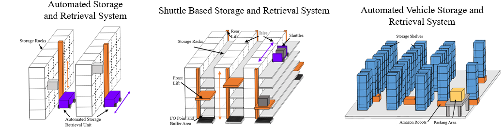
Each has the same structural weakness. The AVS/RS is flexible in how vehicles and lifts are allocated, but it forces sequential vertical and horizontal travel plus waiting time for lift access. The SBS/RS is worse in one specific way: because both lifts share a mast, they cannot pass each other — the upper lift can only reach the I/O point when the lower one is parked at an aisle below it.
The Multi-Track Elevator
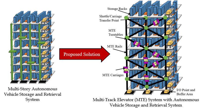
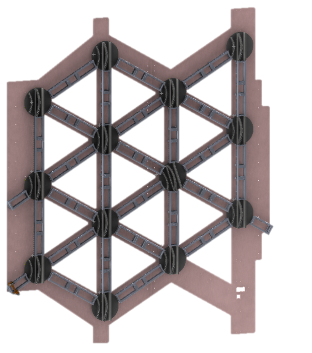
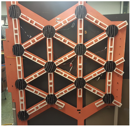
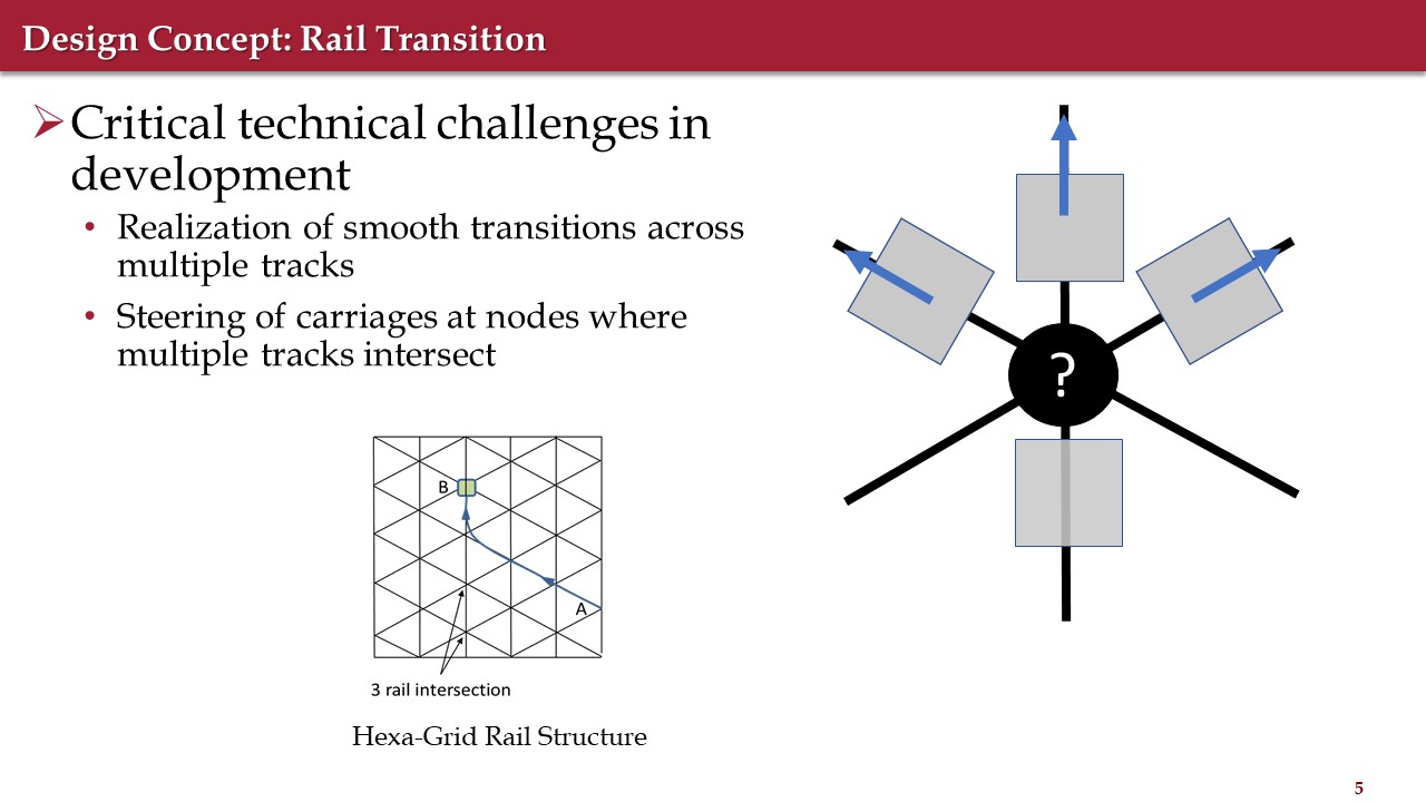
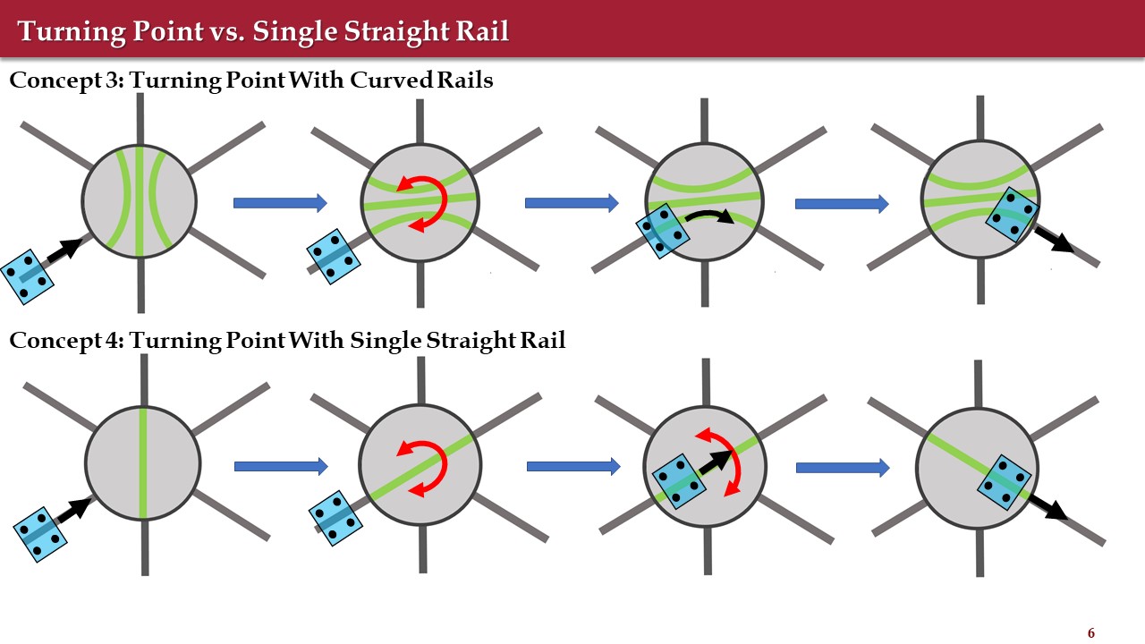
A network of rails with self-powered carriages that move vertically and have freedom in the horizontal direction too. The carriages run on a gridded rail system and change direction at intersections using vertical turntables.
The key difference from a roller-coaster-style comparison: carriages don’t have to stop at switching points. They move continuously across the network of rails, which is precisely what removes the dependence on where the other carriages happen to be.
Designing the rail
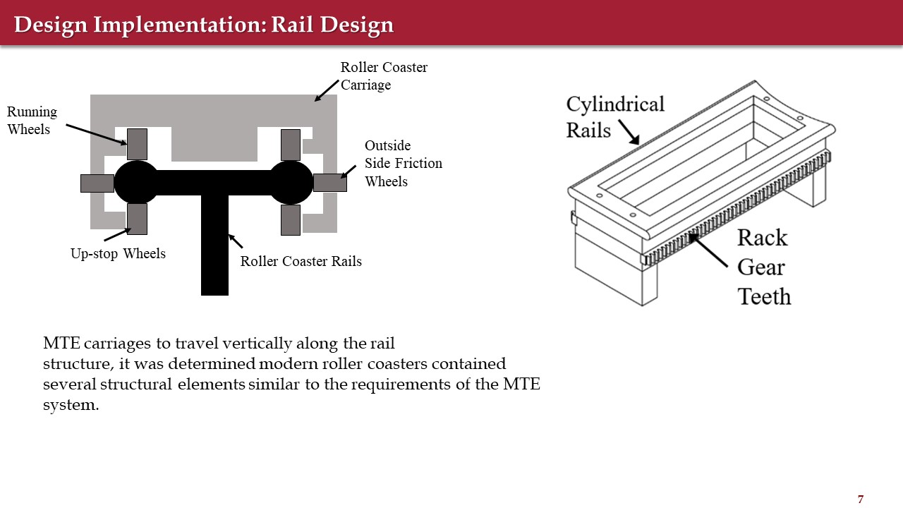
Roller coasters turned out to be the right precedent: three sets of radial bearings act as wheels gripping the rail on three sides, which constrains the carriage completely. To counteract gravity and prevent jamming, the carriage is driven by a pair of individually driven gear motors.
The carriage
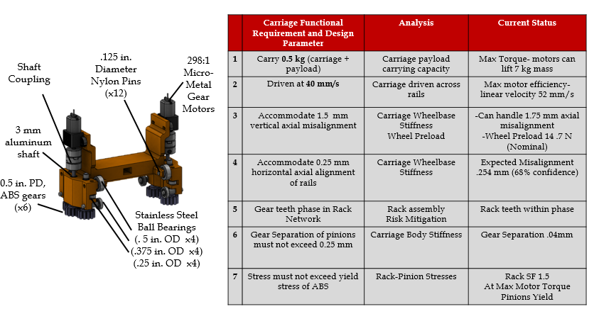
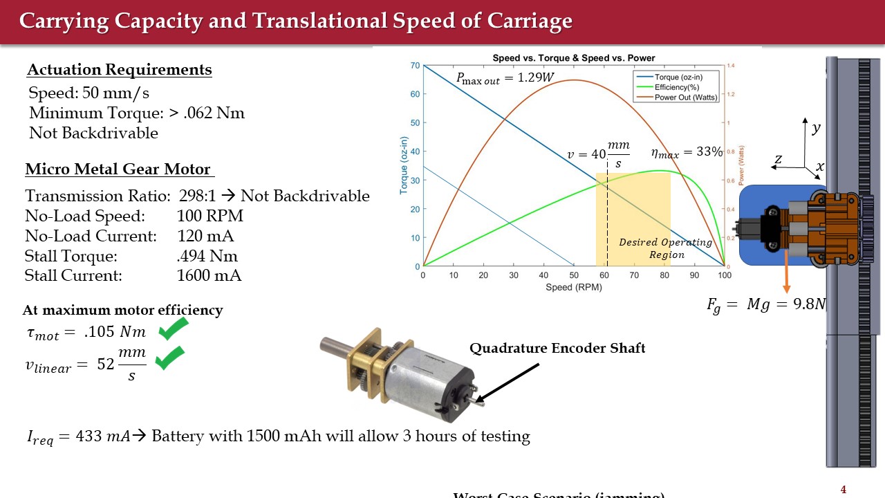
| Requirement | Achieved |
|---|---|
| Carry 0.5 kg | motors lift 7 kg |
| Drive at 40 mm/s | 52 mm/s at max efficiency |
| 1.5 mm vertical axial misalignment | handles 1.75 mm |
| 0.25 mm horizontal alignment | 0.254 mm expected (68% confidence) |
| Gear separation under 0.25 mm | 0.04 mm |
| Stress under ABS yield | rack SF 1.5 |
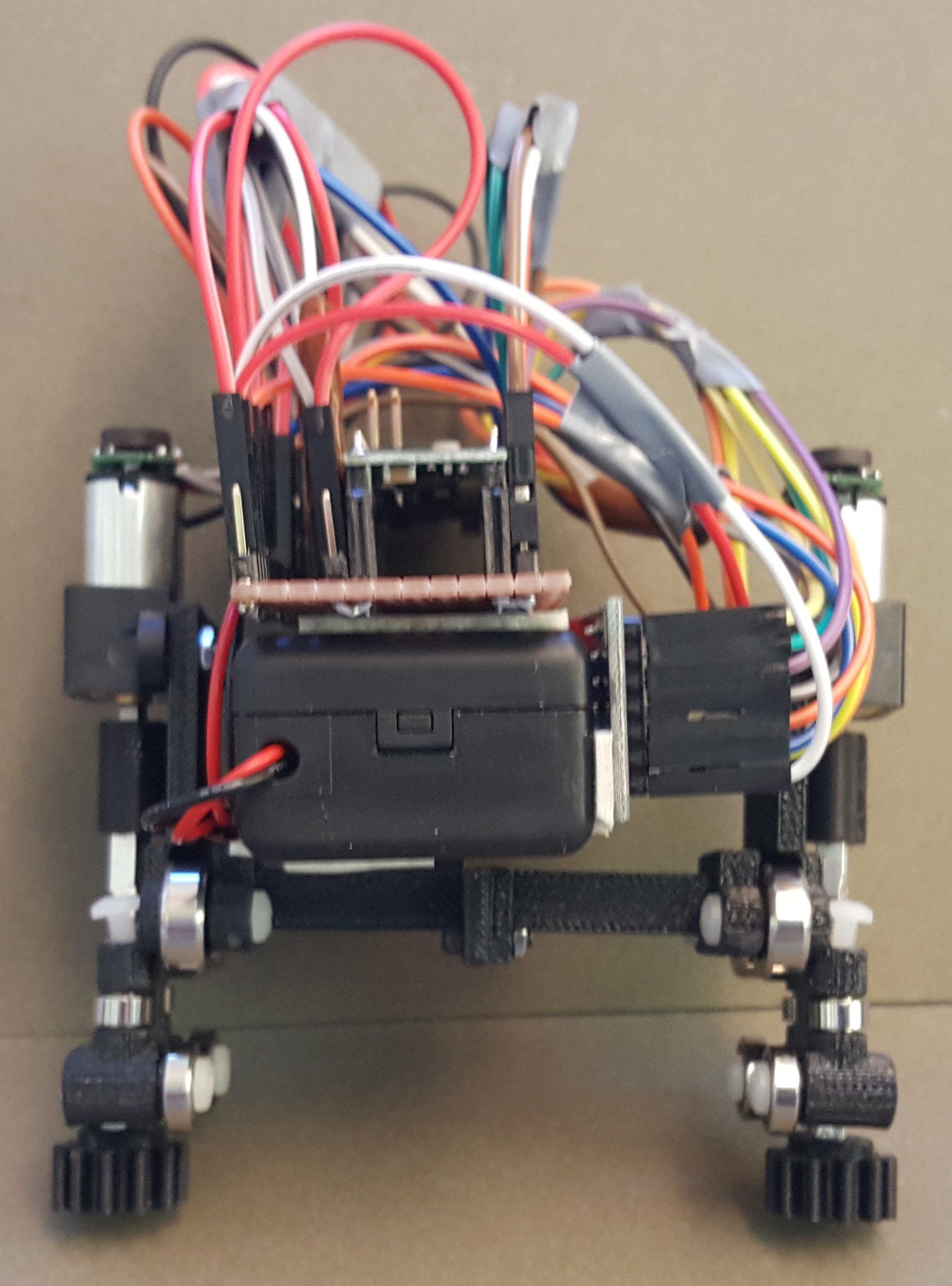
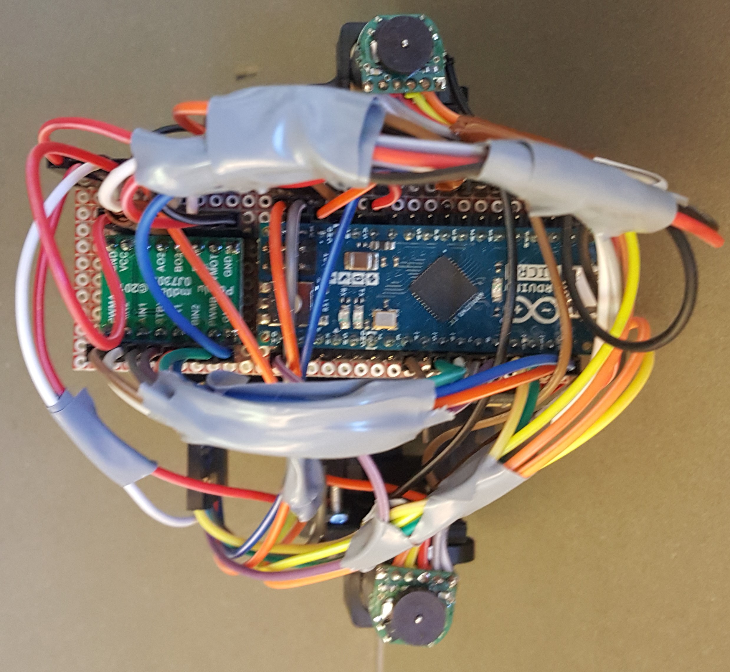
I built the carriage electronics myself, hand-soldering the Arduino Micro, motor driver and IR receivers onto protoboard to fit inside the 3D-printed chassis.
Making the rack and pinion work across joints
Getting the carriage across the connection between the network rails and the turntable rails needed a pinion system that tolerates slight rail misalignment and imperfections in the rack.
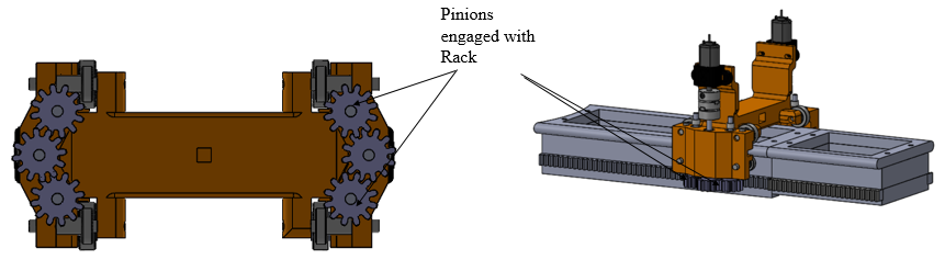
The specific failure mode with a rack-and-pinion network is that rack segments can end up “out of phase” with each other.
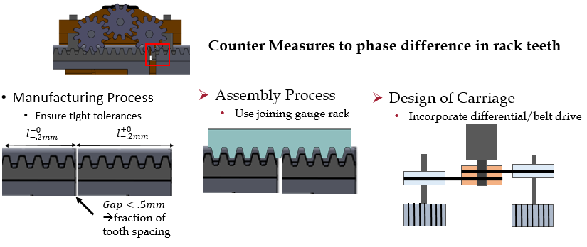
The countermeasure I used when assembling was a joining gauge rack while bolting the segments down. A future prototype would use nylon racks at much tighter tolerances than the 3D-printed ABS ones here — though in practice I saw no noticeable accuracy problems from the printed rack.
The turntable, and the backlash problem
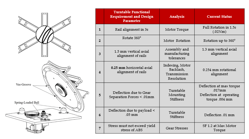
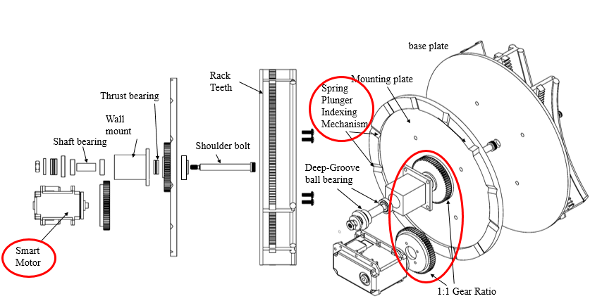
The turntable is driven directly by a Dynamixel smart motor at a 1:1 gear ratio. Which creates the central precision problem of the whole system.
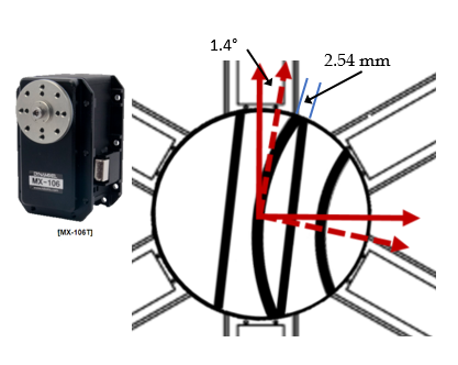
The Dynamixel resolves to 0.088°, but its inherent backlash allows up to 1.4° of angular error — and 2.54 mm of rail misalignment at the rim. The requirement is 0.25 mm. That is an order of magnitude out.
Why a kinematic coupling would have over-constrained it
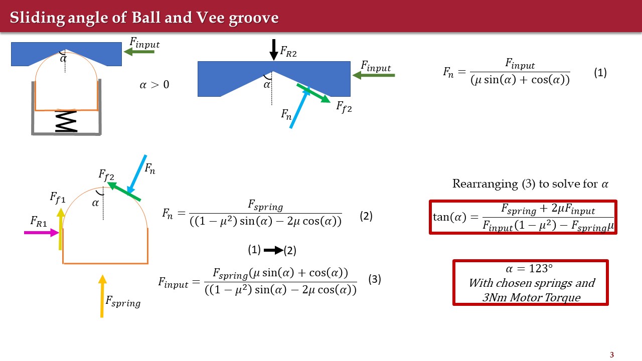
The obvious fix is a kinematic coupling to index the turntable at each rail-mating position. Because the turntable rotates a full 360° on a hexagonal grid, there are only a finite number of positions that need to be accurate.
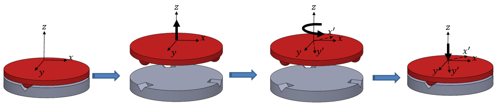
But the turntable already uses a central shaft to hold it on its rotational axis. Adding rigid coupling features on top of that over-constrains the system.
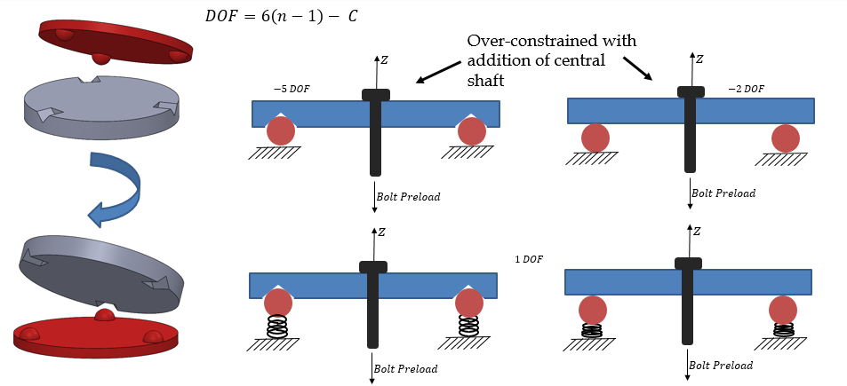
Spring-loading the balls resolves it. With the balls sprung, the system keeps exactly one degree of freedom — and the count stays at one however many balls you add.
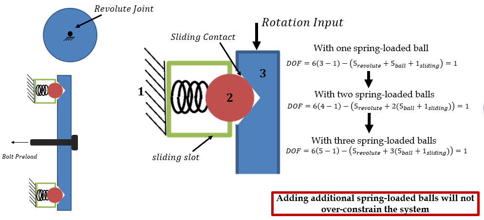
That is the elegant part of the design: it means indexing accuracy can be improved simply by adding more spring-loaded balls and vee-grooves, without ever fighting the central shaft.
How accurate does that make it?
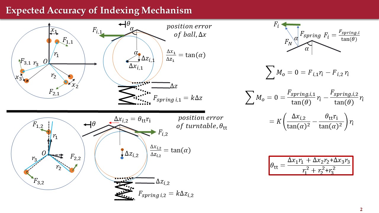
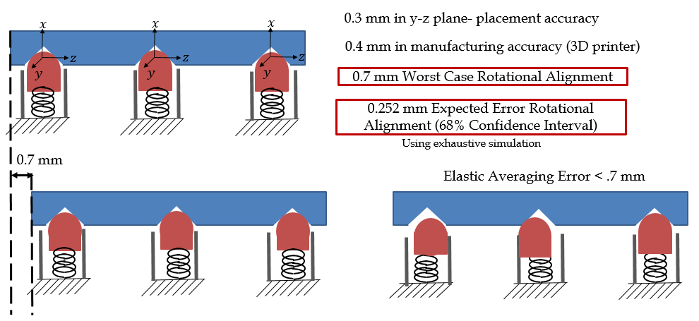
| Dynamixel backlash alone | 2.54 mm |
| With spring-loaded ball indexing, worst case | 0.7 mm |
| Expected error (68% confidence, exhaustive simulation) | 0.252 mm |
The indexing mechanism cuts the misalignment by a factor of about 3.6 in the worst case and by an order of magnitude in the expected case — meeting the system tolerance.
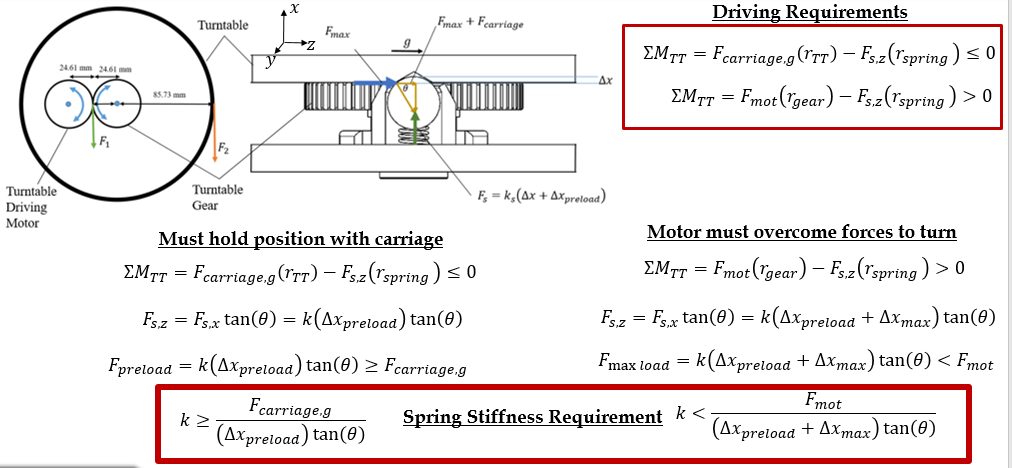
The spring stiffness is bounded on both sides: stiff enough that a carriage’s weight won’t rotate the turntable, soft enough that the motor still can.
Scheduling the carriages
The simplest scheme that both avoids collisions and gives the shortest allowable paths turned out to be a modified Depth-First Search using decoupled path-planning methods.
A standard DFS goes as deep as possible from vertex to vertex before backtracking. The modified version explores all independent simple paths that multiple carriages could take to reach their targets, then picks a final set based on collision avoidance in priority order. It builds an initial priority queue, compares each carriage’s shortest possible paths, and eliminates conflicts by priority. If the local minimum for a given priority queue matches the global minimum path length, it returns immediately — along with the turntables and IR LEDs each carriage is projected to encounter.
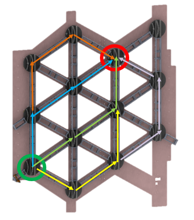
Position sensing is done with IR LEDs of unique signature spaced through the rail network, and an IR reader on each carriage.
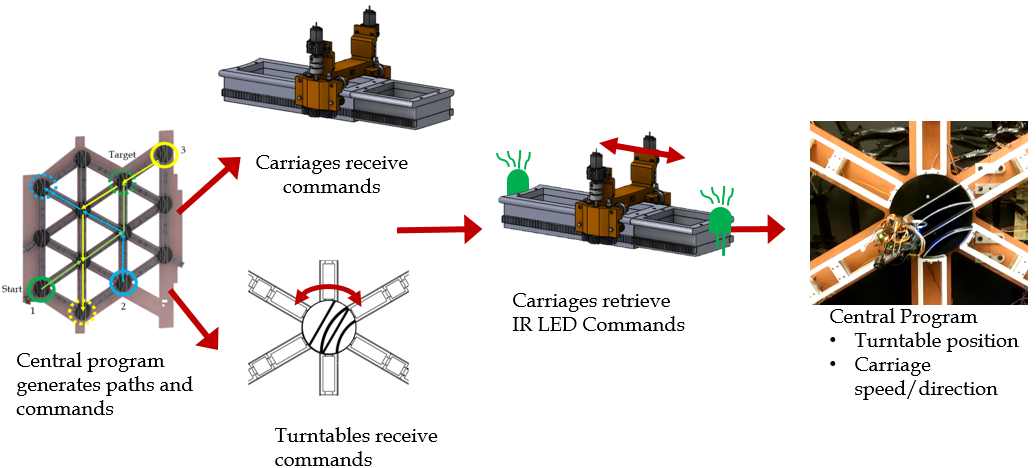
When a carriage passes an IR LED near a turntable, that turntable is triggered to rotate, accept the carriage, and redirect it onto its path.
Does it actually beat the alternatives?
Three systems compared on the time for two or three carriages to retrieve packages and return them to the I/O point: a standard elevator with two inline carriages, a circular motion elevator, and the MTE.
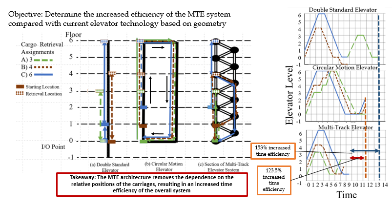
| Compared against | Time efficiency gain |
|---|---|
| Double standard elevator | 153% |
| Circular motion elevator | 123.5% |
Both well over 100%. And the reason is structural rather than incidental: the MTE architecture removes the dependence on where the other carriages are. Carriages never queue for a shared lift and never block each other on a shared mast, because the network gives them independent routes.