Highlights
- Provided machine design expertise to lab members on robotic prototype development and fabrication
- Designed a gantry crane attachment for a robotic crane system manipulating a UR-5 robot and a 15kg aluminum shaft
After I finished my PhD, I stayed on at the d’Arbeloff Lab part-time as a visiting engineer while I worked at Medtronic. The work was a continuation of my PhD. My goal was to build the infrastructure another graduate student would need to carry the peg manipulation work forward: the lab’s gantry crane expanded to carry a UR robot arm and a winch alongside the WinchBot. I also gave machine design help to other lab members working on their own robotic prototypes.
The expanded gantry carrying the shaft across the workspace and around an obstacle.
Choosing the approach
The first idea was a factory-style overhead monorail with carriages that could travel between work cells. I looked at how industry does it, from I-beam trolleys and electric hoists to track switches and turntables, and at what it would take in the lab: curved track, power to every carriage, and a lot of floor space. My recommendation was that a monorail network wouldn’t pay off in the space we had, and that the better path was to add a second girder to the lab’s existing gantry crane. We also chose to mount the UR arm rigidly to start, with the option of hanging it from a WinchBot later.
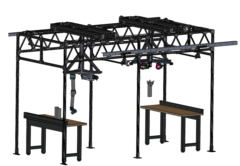
A second girder on the gantry
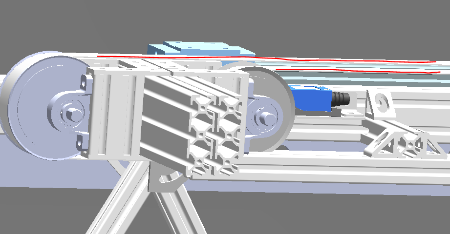
The new girder carries a platform holding the UR arm, mounted upside down, and a winch for the workpiece. The platform had to hold 100 kg. I designed the girder and its belt drives so they would fit on the existing crane without interfering with any of the hardware already there, created the bill of materials, ordered the 80/20 framing and Misumi drive parts, and assembled it, which meant tapping a lot of holes. The UR can be configured for upside-down mounting, and its motion can then be planned with MoveIt.
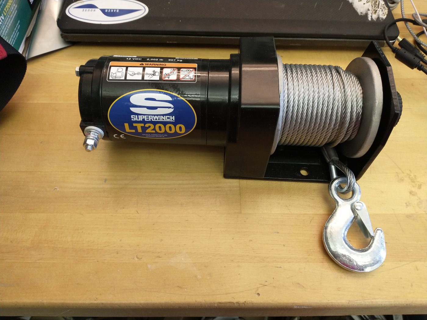
Winches for the workpiece
I tested two options. The first was an off-the-shelf 2,000 lb ATV winch. These are built for pulling, not lifting, and draw about 100 A at full load, so the question was whether one could be controlled and powered in a lab. With PWM velocity control through a 60 A RoboClaw motor controller and a 12 V bench power supply, it raised 68 kg (150 lb) while drawing just over 20 A, so no car battery was needed.
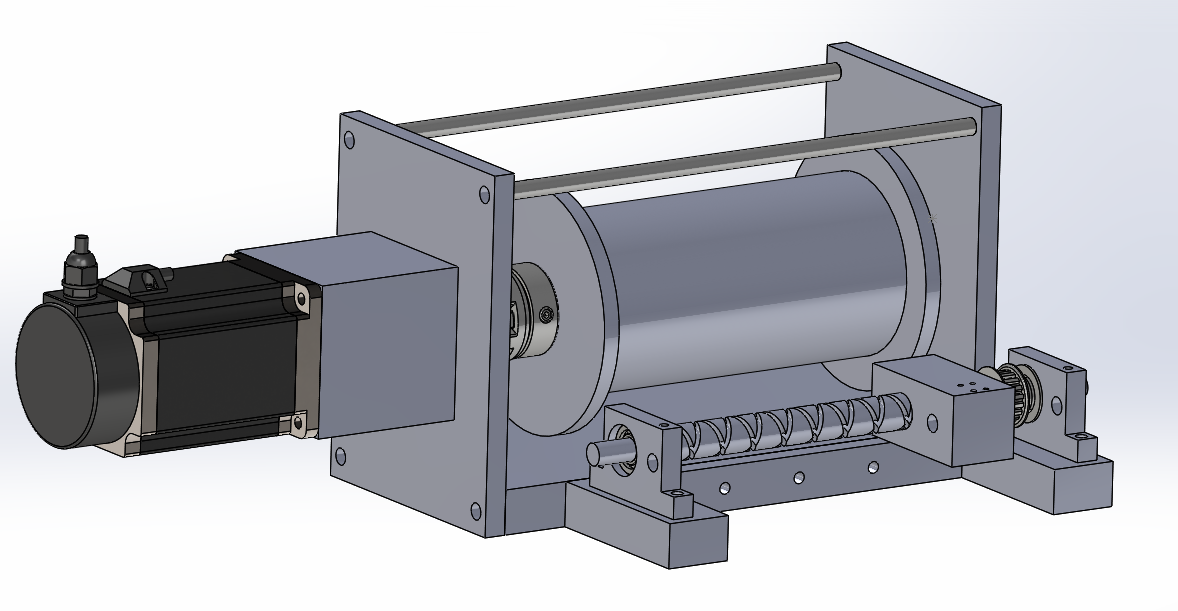
For finer control, I designed a custom winch around a NEMA 34 closed-loop stepper with a gearbox, 432 N·m at stall. A lead screw matched to the cable pitch spools the cable evenly, and a wire guide pulley feeds it onto the drum. The parts came to about $550.
The finished setup
By January 2022 the UR arm and a winch were both hanging from the gantry, lowering the 15 kg peg over the hole, ready for the next student to take over. I also helped move the WinchBot from my PhD onto the lab’s gantry crane for a demonstration, and brought up wedge correction on it there.
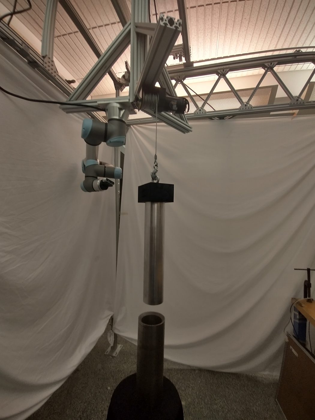
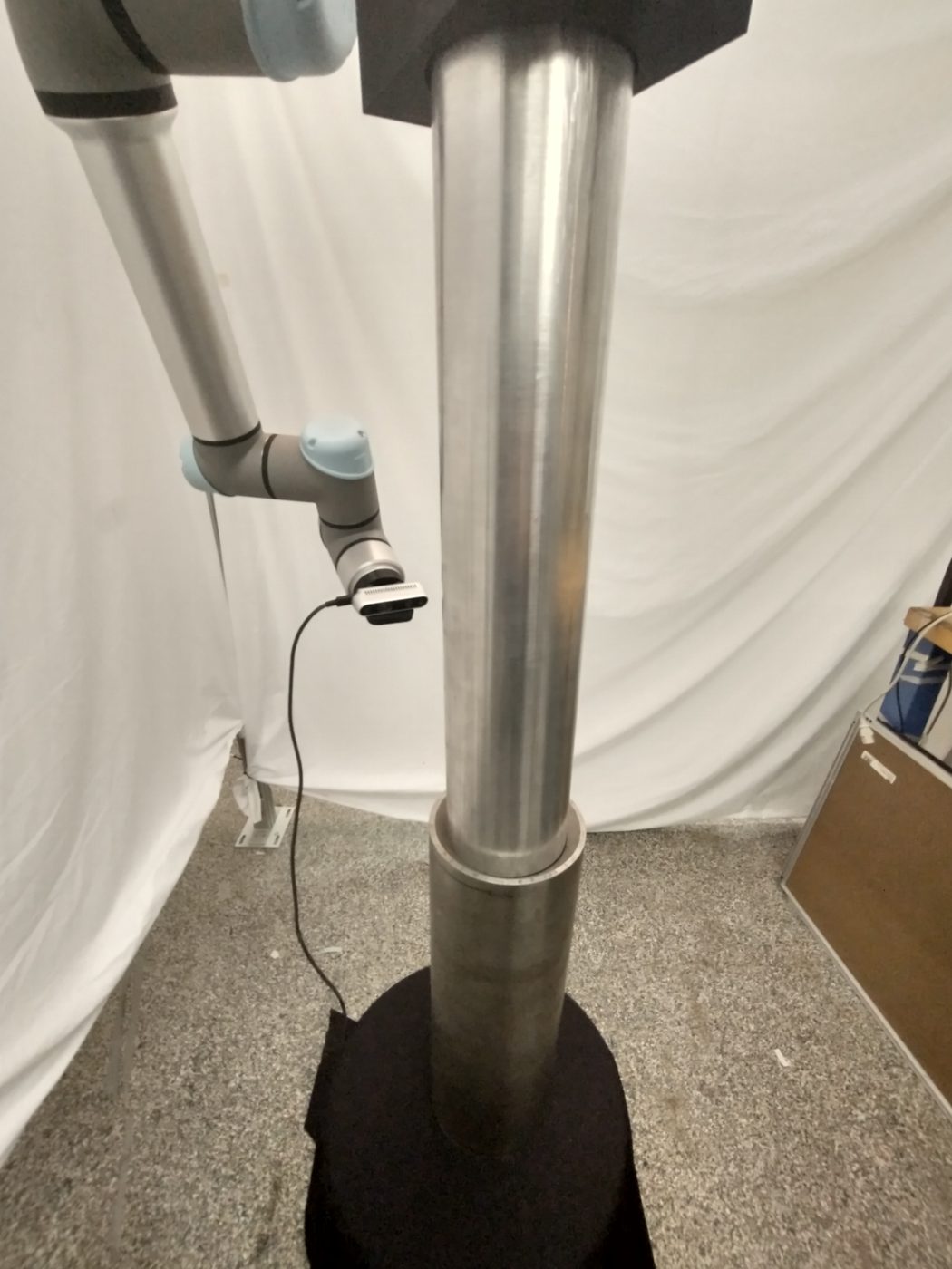
Left: the arm inspecting the shaft with its camera, the first step for the student taking over. Right: the gantry-mounted WinchBot demonstration.