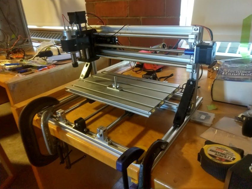
When COVID closed MIT’s shops in March 2020, the 2.72 lathe was one machined spindle into its build (see Lathe Spindle). For the rest of the semester, the hardware was a small off-the-shelf desktop CNC router — a 3018-style kit that sells for about $200 — plus a dial indicator and a luggage scale. The job was to do the machine design backwards: decide what the router should be able to do, measure what it actually does, build a model that explains the gap, and use the model to fix it.
What it should do
I framed it as a hobby engraver cutting acrylic signs and coasters and set the requirements from what a user would notice. In-plane (XY) error is the obvious one — a circle coming out as an oval, letters running together. Depth (Z) matters less, but it isn’t free: the V-bit’s cut width changes with depth, so depth variation shows up as a line that swells and thins.
| Requirement | Value |
|---|---|
| Material | Acrylic |
| Depth-of-cut variation (Z repeatability) | 0.002 in max |
| In-plane variation (XY repeatability) | 0.004 in max |
| Depth of cut | 0.005 in max |
| Feed rate | 12 in/min max |
Acrylic’s specific cutting energy, applied to the recommended chip load at that depth and feed, gives a cutting force of about 10 N. Dividing the XY tolerance between X and Y by root-sum-square turns those numbers into minimum stiffnesses at the tool tip: 140 N/mm in X and Y, and 190 N/mm in Z.
What it actually does
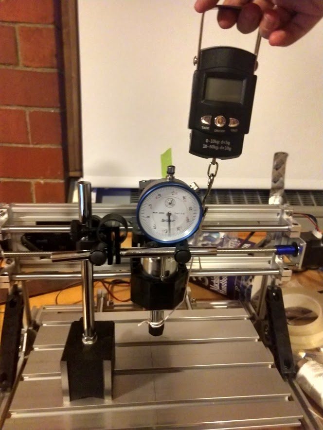
I clamped the router to a desk and loaded it at the collet with the scale, reading deflection on the dial indicator three times per direction. Every value is a mean with a 95% confidence interval from the t-distribution. The full structure, loaded at the collet, came in at 90, 128 and 18 N/mm in X, Y and Z. It misses the requirement on all three axes, and in Z by an order of magnitude.
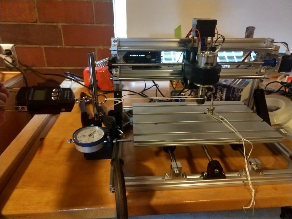
A single number doesn’t tell you what to fix, so I ran six experiments that isolated one subsystem at a time, moving the load point and the indicator base up the structural loop from the frame to the tool.
| Subsystem | kx | ky | kz |
|---|---|---|---|
| Frame through ground | ∞ | ∞ | ∞ |
| Y platform | 1000 ± 270 | 300 ± 16 | 500 ± 36 |
| Extrusion gantry, as a cantilever | 400 ± 74 | 290 ± 21 | ∞ |
| Z carriage + spindle bracket | 88 ± 6 | 416 ± 10 | 67 ± 3 |
| Spindle bracket alone | 90 ± 8 | 86 ± 6 | 261 ± 50 |
| X carriage, centred | 150 ± 9 | 97 ± 6 | 90 ± 5 |
Stiffness in N/mm. “∞” means no deflection was visible on the indicator.
The culprit is the plastic spindle bracket. It sets the X stiffness on its own, and together with the Z rails and the X carriage it dominates Z. The aluminium frame and the gantry extrusions are stiff enough that their contribution is mostly as a lever arm for Abbe error.
Modelling it
I built a homogeneous transformation matrix (HTM) model of the structural loop. It uses six coordinate systems chained from the Y table to the tool tip, sketched and dimensioned off the real machine, with each link’s stiffness taken from the experiments. The model propagates load-induced and Abbe errors to the tool tip and gives the whole machine’s stiffness.
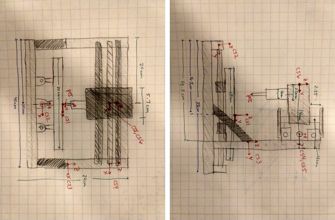
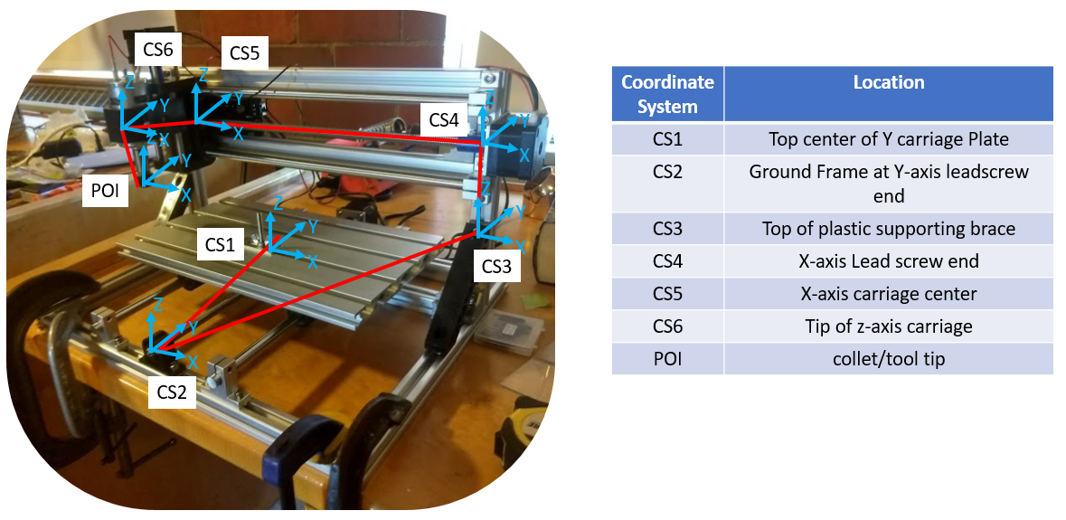
The model put the machine at 122, 140 and 257 N/mm. That’s the same order as the measurements, not a match: it idealises the extrusions as clean cantilevers and leaves out the compliance of their bolted joints. Ranked by contribution, the plastic Z-axis cantilever came first in all three axes. Next came the X-axis leadscrew and the X carriage’s torsional stiffness, amplified into Abbe error at the point where the gantry, the X leadscrew and the compliant X rails meet.
Motion and repeatability
The drive side matters less than the structure. One microstep — 200 steps per revolution, 16 microsteps and a 4 mm lead — is 1.3 µm, far finer than either the dial indicator or the structure can resolve. I measured the X axis at the near, middle and far end of its travel with 0.2, 2 and 20 mm moves, five times each:
- Returning to a start point is tight. At every position and stroke length, return-to-zero landed within a few microns.
- Moves come up short. A commanded 20 mm move travelled 19.88 to 19.92 mm, and accuracy got worse further from the motor. That points to friction the torsional leadscrew model doesn’t capture, most likely the seals on the linear bearings.
- It drifts. After 50 round trips of 200 mm, the carriage had lost 0.127 mm, enough to visibly warp a long engraving with many stops and starts.
Fixing it
With the structure as the main problem, the most effective cheap change was the rails. The X carriage visibly twists on its 10 mm guide rods under load at the collet. Going to 15 mm rods in the HTM model more than tripled the machine’s stiffness, and every axis cleared its requirement:
| 10 mm rails (stock) | 15 mm rails | |
|---|---|---|
| Stiffness kx / ky / kz | 122 / 140 / 257 N/mm | 398 / 450 / 955 N/mm |
| Total Y error at the tool | 925 µm | 242 µm |
| Total Z error at the tool | 195 µm | 44 µm |
At McMaster prices, the larger rods add about $32 to a $200 machine. That’s a lot at retail, but plausible at kit-maker wholesale prices. The other changes on the list are smaller ones:
- a one-piece aluminium bearing block, to stop the rails going out of alignment with each other
- a flexure between each leadscrew nut and its carriage, to stop the two constraining each other
- a real shaft coupling in place of set screws
- leadscrew mounts that route cutting loads into the frame rather than into the stepper motors