The Spring 2020 project in 2.72 was a small benchtop lathe, designed and built by teams of six. Each team owned the engineering behind every subsystem — the error budget, the cutting-force model, the bearing selection, the drawings — and then had to machine the parts to the tolerances it had set itself.
Our group, Knurled but not Broken, started with the spindle, because everything else on a lathe is measured against it. We designed it, drew it and machined it, and every key dimension checked in spec at the machine. Then, in the second week of March, MIT sent students home. The spindle design review went ahead over video on 6 April. The lathe was never assembled, and the rest of the semester became the desktop CNC router assessment.
The design review deck is a team presentation: all six of us built and presented it together. My slides in it are the free-body diagram, the spindle stiffness model, the spindle geometry and the system error budget. The rest is my teammates’ work.
Requirements and the error budget
The course staff set the system-level requirements:
| Requirement | Value |
|---|---|
| Material to cut | 12L14 steel |
| Material removal rate | 0.08 in³/min minimum |
| Surface finish | 63 µin maximum |
| Repeatability | 50 µm maximum |
| Spindle runout | 50 µm maximum |
| Machine life | 2000 hours minimum (one working year) |
A 50 µm root-sum-square budget across three axes allows 28.86 µm per axis. The spindle started with a third of that: about 11.3 µm of deflection at the tool. The team’s cutting-force model ran the required removal rate in steel at the worst case — zero rake, a tool–workpiece friction coefficient of 2 — and gave up to 200 N of cutting force, 400 N of thrust and 200 W of cutting power. Divided into the deflection allowance, those loads set the spindle’s stiffness requirements: at least 35 N/µm axially and 17 N/µm radially.
My part: loads, stiffness and the error budget
I built the spindle’s free-body diagram: bearing reactions, pulley forces, and the cutting, thrust and radial forces from the tool, with the torques from the pulley, the bearings and the cut.
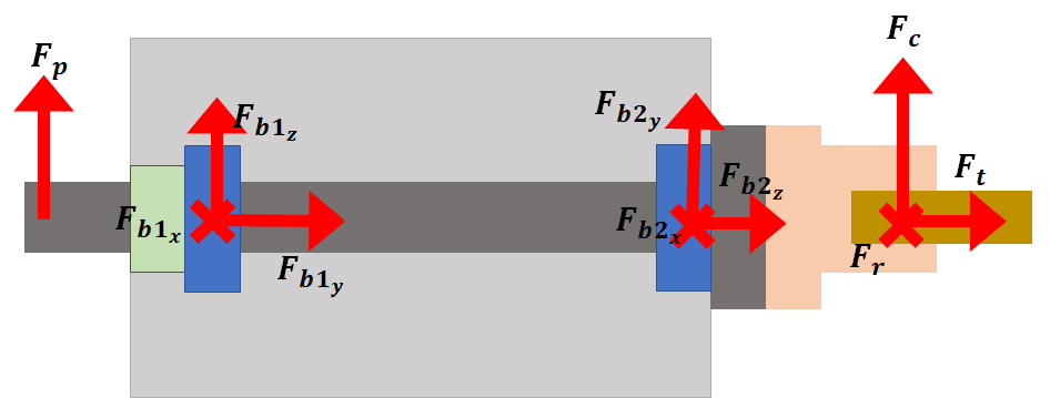
From it I built a stiffness model of the spindle: shaft, bearings and housing as springs in series, set up separately for the axial and radial load paths. It gave the team its most useful design rule: the bearings set the axial stiffness, and the shaft sets the radial stiffness. That split steered the geometry decisions that followed. Bearing spacing and the overhang to the chuck went after radial stiffness through the shaft, and preload went after axial stiffness through the bearings.
I also owned the error budget, modelling the spindle and headstock together under thrust, cutting and thermal loads. At the review, it put the tool-tip error at 8.0 µm radially and 20.2 µm axially, 21.7 µm RSS. That’s inside the 28.86 µm per-axis allowance, with the axial direction as the one with the least margin. It came with a caveat to close before assembly: runout still had to be measured and added in.
The team spindle
A 0.75 in steel shaft on a pair of Timken LM11949/LM11910 tapered roller bearings 2.6 in apart, preloaded through a spring washer. Timken GR236 grease was the cheapest grease that kept friction heat under 50 W per bearing, and a motor-to-spindle belt ratio of 0.52 or less did the same for the drive. The chuck threads onto an M14 × 1 nose, a 3/4-16 thread behind the rear bearing carries the preload nut, and the tail is keyed for the pulley.
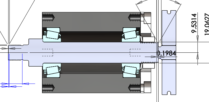
I drew the shaft for manufacture, which is where the error budget turns into numbers a machinist can actually hold. The two bearing seats are held to ±0.0005 in: the front seat at 0.752 in, a light press fit that locates the fixed bearing, and the rear at 0.749 in, a slide fit so the rear bearing can float and take up the preload. The seats and shoulders are dimensioned from a common datum axis, and the shoulder fillets are toleranced one-sided so they can’t hold the bearing cones off their shoulders.
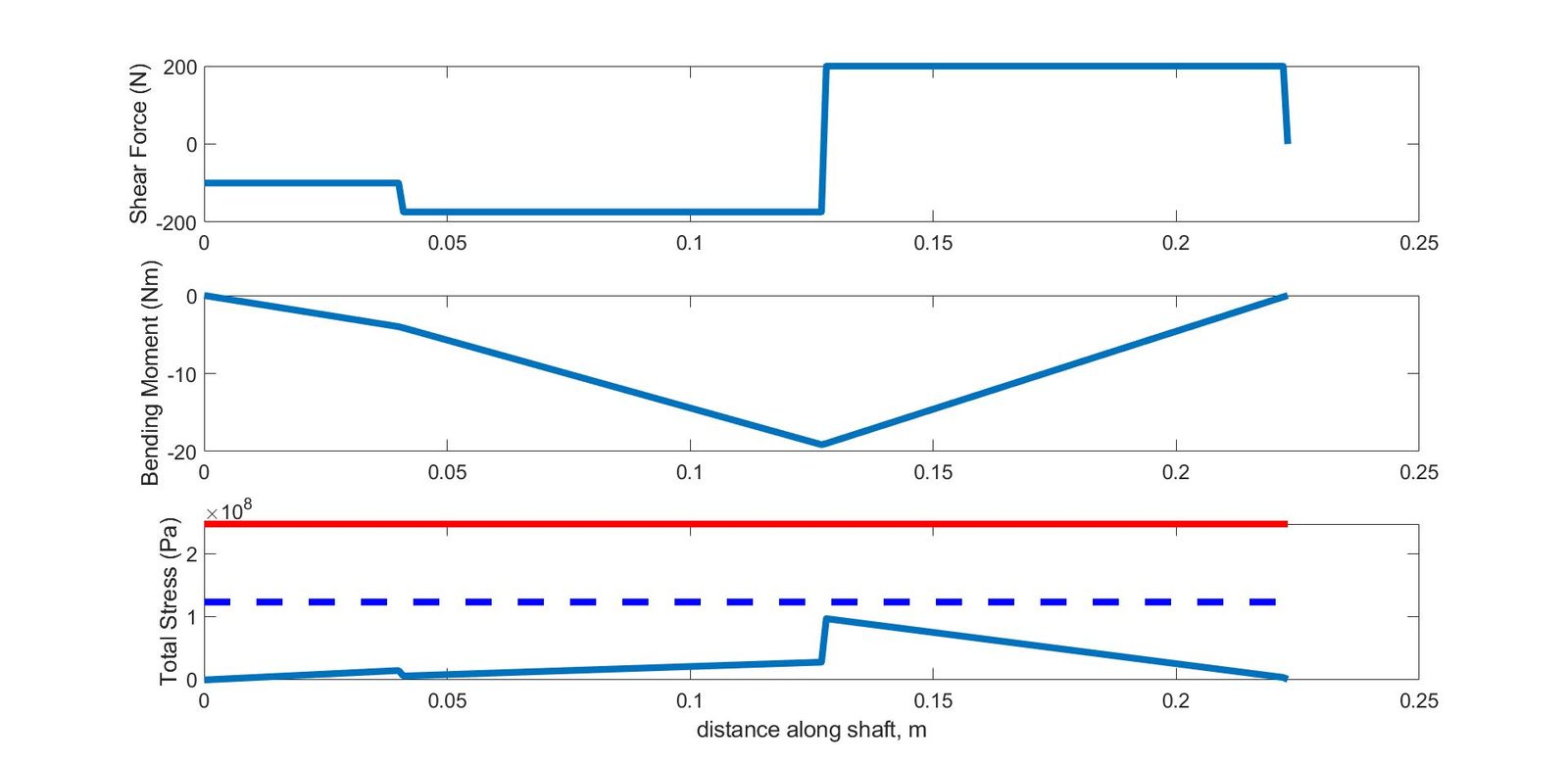
The team’s fatigue check along the shaft put the peak bending moment, about 19 N·m, at the front bearing. The stress there, roughly 90 MPa with the stress concentration included, sits below the shaft’s 137 MPa endurance limit and well below yield.
Machining it
We made the housing from aluminium bar and the shaft from steel on the shop’s manual lathes, in the last weeks before the shutdown.
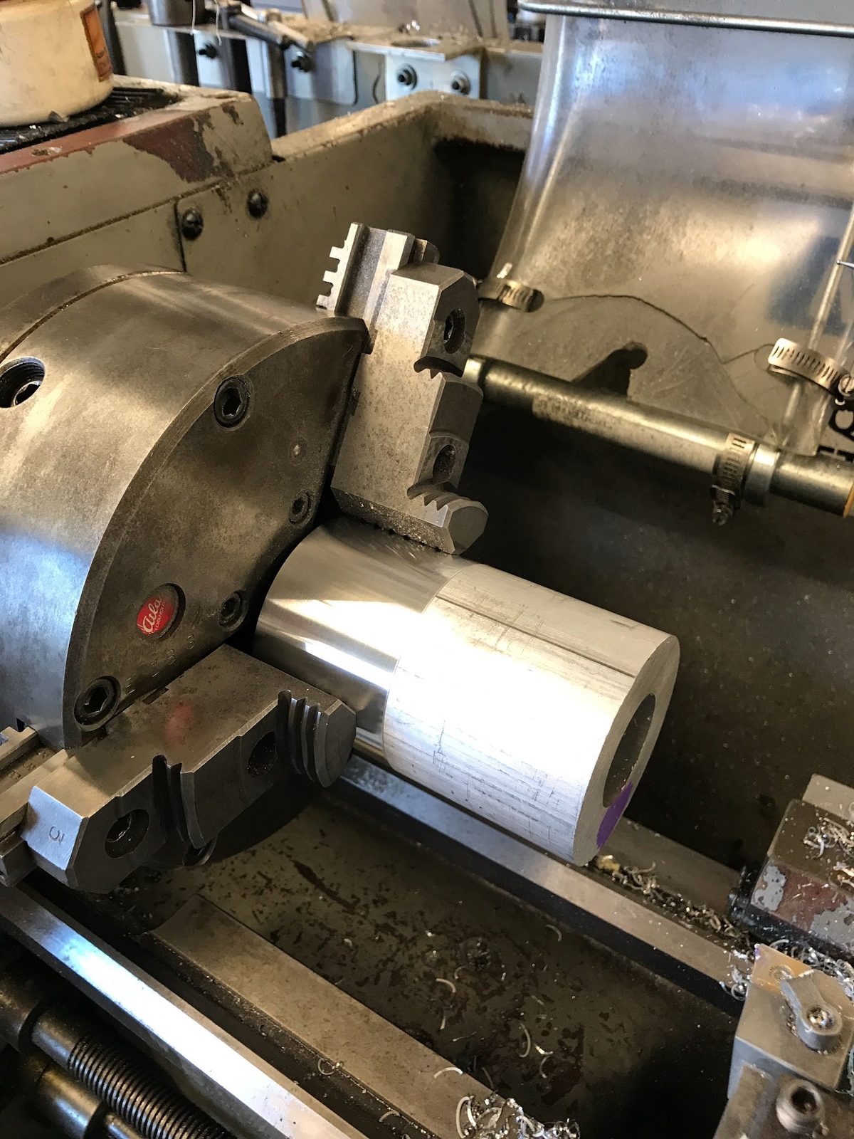
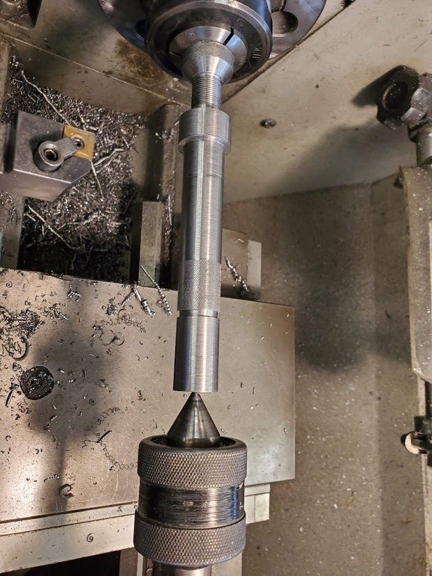
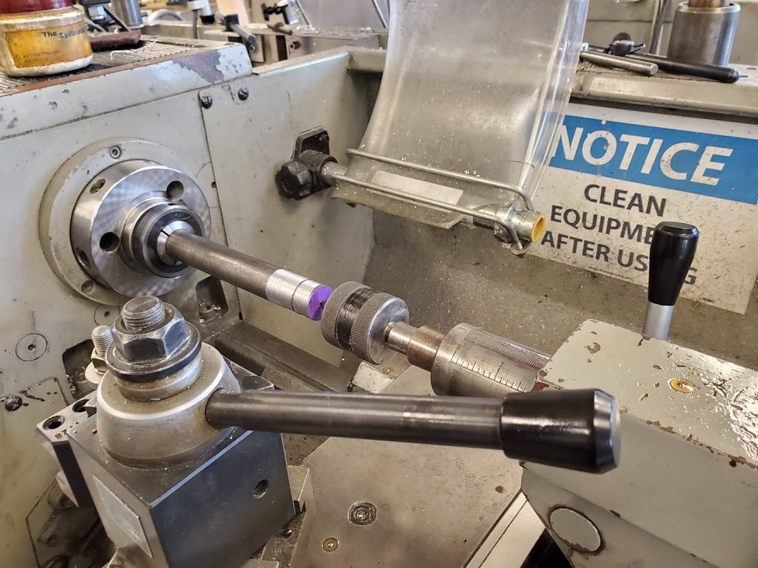
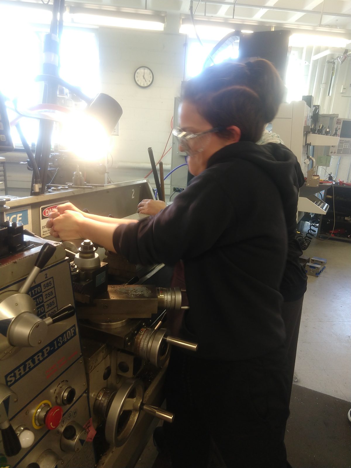
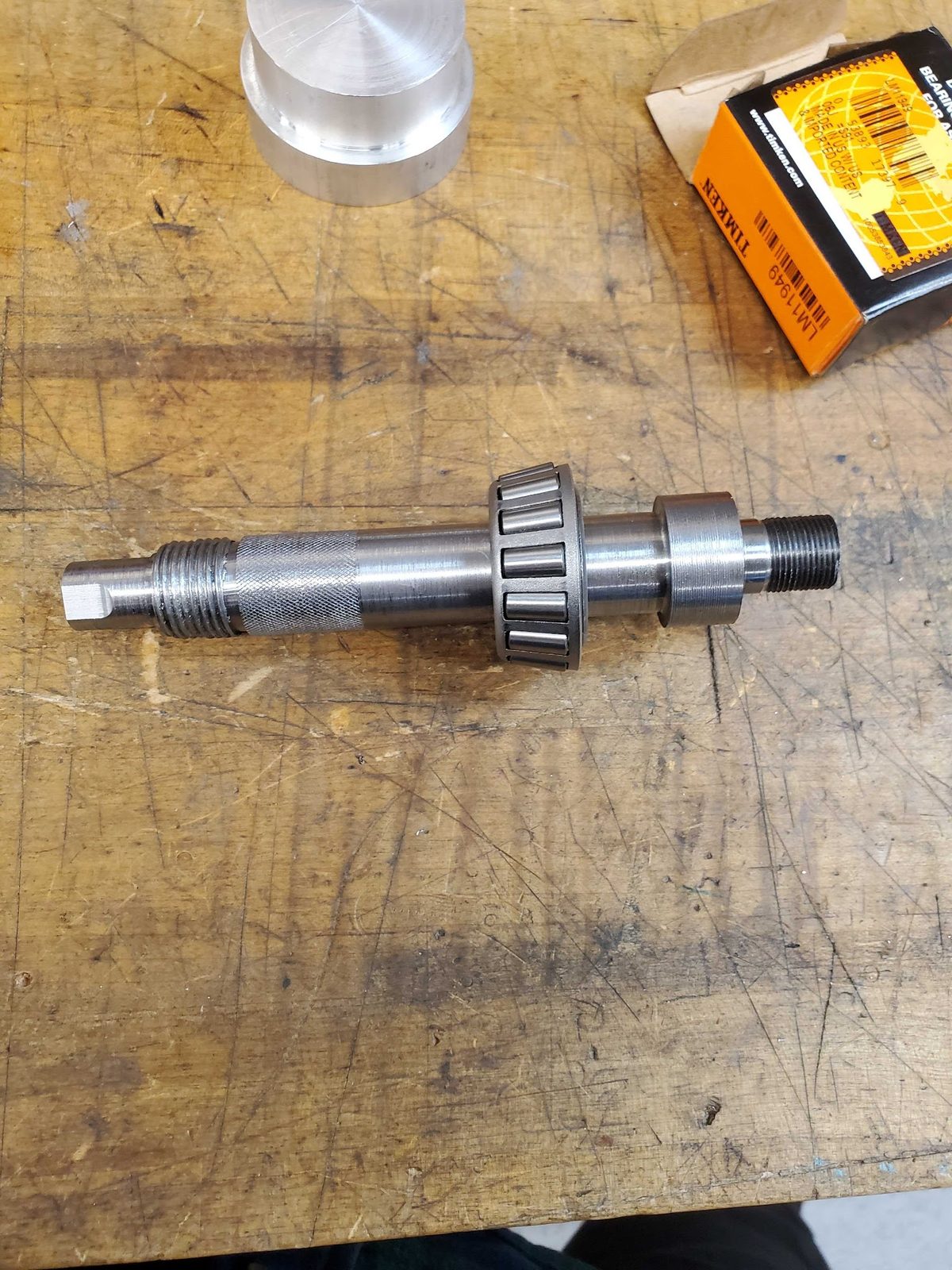
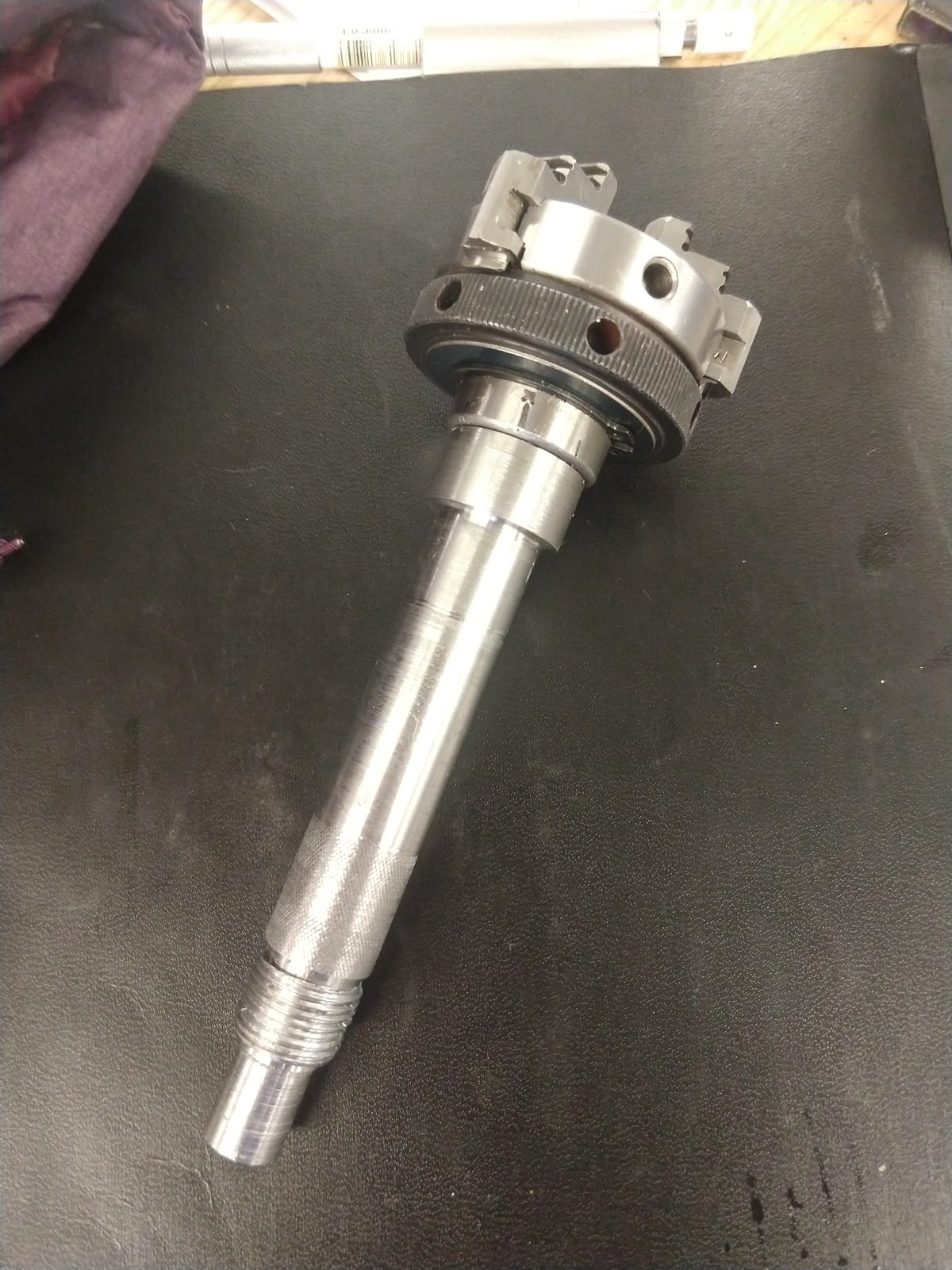
By the design review, the spindle was complete and every key dimension had been checked in spec at the machine. The shutdown came before anyone could record those measurements, assemble the spindle into the headstock or test it. It also ended the team’s proposed graduate extension: strain-gauging the tool post to measure cutting forces directly, or adding an encoder readout and power feed.
After the shutdown: an alternate spindle, on paper
With the shop closed, the April assignment was individual: take the team spindle apart analytically and design a better one. I re-apportioned the budget over the two directions the part is actually sensitive to, 35.35 µm each, and split that three ways, leaving the spindle 11.77 µm per direction. Against that, the team design’s roughly 20 µm of axial deflection at the tool was well over, and the stiffness model said where to push: shaft diameter for radial stiffness, and bearing arrangement for axial.
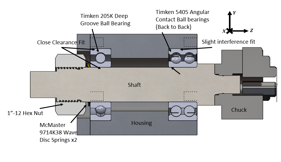
My alternate attacks both. The shaft grows from 0.75 in to 1.00 in. The front bearing becomes a Timken 5205K double-row angular contact bearing, mounted back to back for axial stiffness, and the rear becomes a Timken 205K deep-groove ball bearing floating in a close running fit. Two wave disc springs under a 1”-12 nut set the preload.
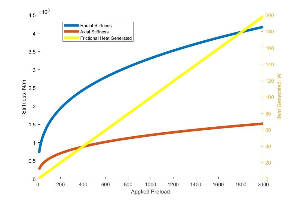
Preload is the main tradeoff. More preload stiffens the bearings but also costs friction heat and motor power. I swept it: radial and axial stiffness rise steeply at first and then flatten, while frictional heat climbs linearly. I settled on 300 N, which gets most of the stiffness while holding heat generation under the 100 W limit.
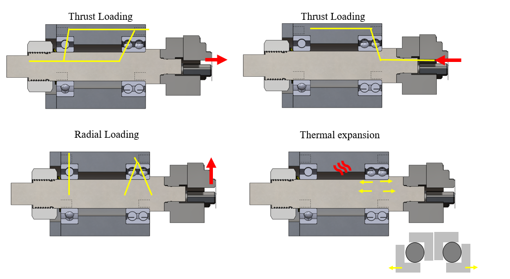
The back-to-back arrangement also handles heat well. As the shaft warms and grows, the inner races move outward and slightly unload the preload rather than piling more on. The deep-groove bearing, preloaded axially so it behaves like an angular contact bearing, relaxes the same way.
| Team design | My alternate | |
|---|---|---|
| Shaft diameter | 0.75 in | 1.00 in |
| Bearings | Timken LM11949/LM11910 tapered roller pair | Timken 5205K double-row angular contact + 205K deep-groove ball |
| Spindle + headstock deflection, X / Y / Z | 8.6 / 8.6 / 19.7 µm | 1.9 / 1.9 / 8.3 µm |
| Runout | 0.002 in | 0.0005 in |
| Bearing life, 24/7 operation | 5.9 years | 5 years |
| Bearing cost | $7.07 per bearing | $30 per set |
All three directions come in under the 11.77 µm budget, and runout drops by a factor of four. The costs are about four times the bearing spend and a slightly shorter life, set by the deep-groove bearing. The write-up closed with a press-and-preload assembly procedure. The preload is set by displacement, turning the nut against a dial indicator until the disc springs reach their rated working deflection, and then checked by pulling on the chuck with a spring scale until the shaft starts to move.