An assembly planner needs to know which parts block which. Working that out by hand is tedious and easy to get wrong, so this derives it straight from the CAD geometry instead.
The problem: nobody wants to fill in the matrix by hand
Most approaches to assembly and disassembly planning pair a graph representation with a search algorithm. Our team used Ant Colony Optimization to search. But every one of those methods needs the same input first: a disassembly matrix encoding which parts block which other parts, and along which directions.
That matrix is almost always built either manually or through a series of user interactions. For anything with a realistic part count that is slow, and worse, it is error-prone in a way that quietly poisons the search. One wrong entry and the planner confidently produces a sequence nobody can physically execute. Building those matrices by hand was the single biggest time sink in our earlier work, which is what sent me looking for a way to read them out of the CAD.
The structure I built to test it
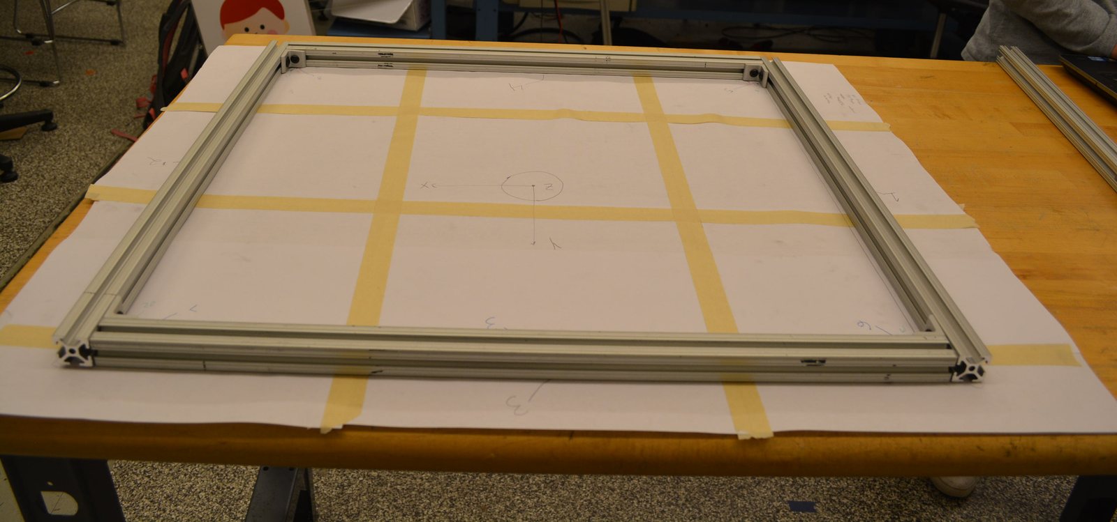
I designed and built a frame from 80/20 aluminium extrusion, T-nuts, 1/4-20 bolts and corner gussets. It is small enough that I could check the generated matrix by hand, and awkward enough to be interesting: 80/20 has a real assembly-order constraint built into it. Once a corner gusset is bolted on, it closes off the channel the T-nuts slide into, so any T-nut you forgot is a T-nut you cannot add without taking the corner apart again. That is exactly the kind of precedence a planner has to respect.
From meshes to a matrix
The pipeline starts from STL meshes exported out of the SolidWorks assembly. Each mesh is
read into MATLAB with the open-source stlread and turned into a filled polygon, positioned
at its origin in the assembly.
To find interference, each part is perturbed about 5 cm along X and Y and then checked for collision against every remaining part. The frame is planar, so Z adds nothing here and is skipped. Collision checking uses the Gilbert-Johnson-Keerthi (GJK) distance algorithm, which is fast enough to run the full pairwise, multi-direction sweep the matrix needs.
Fasteners are the part geometry alone won’t tell you about, so I added a fastening mate: a function that fixes two parts to each other and writes the fastener itself into the disassembly matrix. That covers the T-nut-and-bolt relationships that make the 80/20 frame behave the way it does.
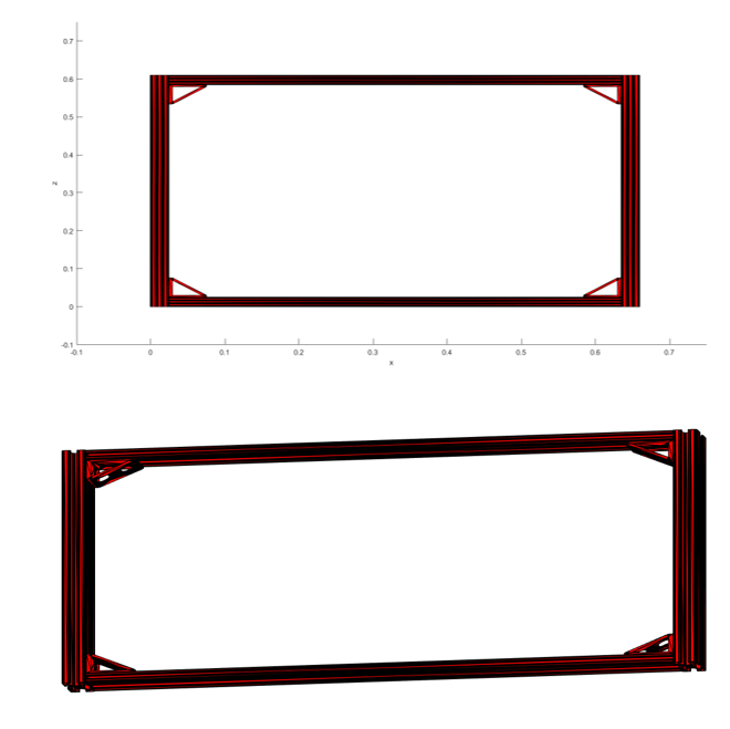
What comes out is the disassembly matrix the planner needs, derived from the model rather than typed in by a person.
What the team did with it
The matrix fed the planning side of the project. Our baseline was Ant Colony Optimization; from there the team extended it in two directions. TACO (Team Ant Colony Optimization) splits the ants into teams that share one matrix and one visited list, so a plan can be split across several robots, with a shared start state and a no-op action so an agent can wait. MOTACOS adds multi-objective search on top, balancing competing costs instead of optimising one number.
The whole thing ran over ROS: a supervisor node publishes the problem, the planner node computes the sequences, and each robot subscribes to its own command topic.

Our class demonstration: the planner sequencing a disassembly and handing the steps to the robots.
Paper
The team’s final report covers all of it. My section documents the CAD-to-matrix work: the existing approaches to extracting disassembly information from CAD (precedence relationships, geometric constraints, and interference-based methods), the MATLAB implementation, and the frame design the planning side tested against.
Using Ant Colony Optimization To Solve The Assembly Planning Problem — four-author 16.412/6.834 final report. My section: “Using CAD Meshes to Extract Disassembly Matrix Information for use in the Assembly Planning Problem.”
The repository holds my MATLAB implementation, the CAD and STL geometry, and the report. Third-party mesh and collision-detection utilities used during development are noted as dependencies rather than vendored in.