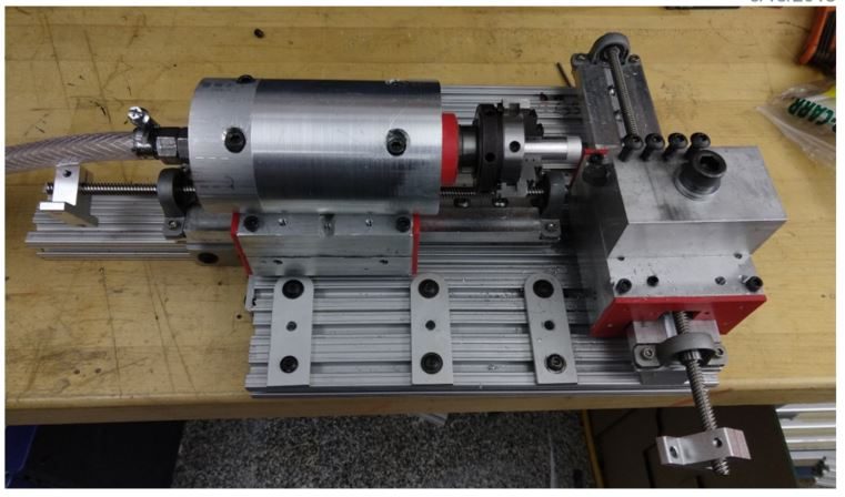
The final project in 2.77 is a semester-long build: design and machine your own small precision lathe from raw stock, with every axis backed by a real error budget rather than “it looks stiff enough.” Mine came together as a T-based lathe — two linear motion slides (the X and Z axes, Weeks 5–7) and a rotary spindle (Weeks 8–10), assembled into one machine in Week 11 and written up in full in Week 12. In a conventional lathe the tool moves on two axes while the spindle stays fixed; in a T-based lathe, the spindle itself rides on one linear axis and the tool on a second axis perpendicular to it, forming a “T.”
Design approach
Every subsystem traces back to the same error budget: start from a total accuracy target for the finished part, apportion allowable error across geometric (manufacturing and assembly) and load-induced (stiffness) sources for each axis, then design components against those individual numbers. Targeting 100 µm total part accuracy, cutting-force predictions (100N tangential, 70N radial/thrust for a 1mm facing pass in aluminum) set a required system stiffness of about 6 N/µm per axis.
The linear motion modules went through several sketch-model concepts — a two-rail slider came out most sensitive to manufacturing error, and its stiffness varied depending on where the carriage sat along the rail — so I settled on a boxway design instead: an aluminum carriage riding on Delrin bearing pads (chosen for stiffness and low friction), preloaded against a T-rail with set screws to eliminate rattle. The spindle used J3 Iglide plain bearings from a sample kit IGUS brought to class, turned into a housing machined from 3” 6061-T6 stock, with a mini 3-jaw chuck threaded onto the shaft.
Testing the carriage’s rotational stiffness turned up a real modeling gap: measured roll stiffness matched the prediction well, but measured yaw and pitch stiffness came in at roughly 1/10th and 1/20th of predicted — the original model treated the whole carriage as a simply-supported beam, which turned out not to capture the real compliance path.
Results — closing the loop
I cut two test parts: one held in the three-jaw chuck, one threaded directly onto the spindle shaft, specifically to separate the lathe’s own accuracy from the chuck’s contribution to error.
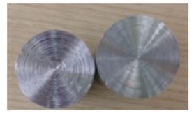
Each part got two independent measurements: a dial indicator dragged across the surface in 30° increments to map overall contour (accuracy), and interferometer surface-finish readings (repeatability).
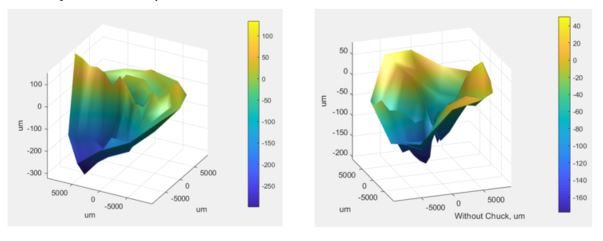
The contour plot for the direct-spindle part revealed something the dial-indicator data alone wouldn’t have shown outright: a consistent slant suggesting the two linear axes weren’t quite perpendicular. Working backward from the contour, I calculated that misalignment at 1.45°.
The numbers that mattered most: accounting for two standard deviations (95% confidence), the part faced directly on the spindle came out accurate to within 112.5 µm, and the part faced through the chuck to within 187.9 µm. My error budget spreadsheet had predicted a worst-case error of 255.7 µm (233 µm from loading, 22.7 µm from random error) — meaning the real lathe beat its own worst-case prediction by about 70 µm. That’s just outside the original 100 µm target, but well inside the predicted error band, which is the result I actually cared about: the model and the physical machine agreed.
What I’d change
Two things, with more time: correct the 1.45° axis-perpendicularity error the contour plot uncovered, and revisit the yaw/pitch stiffness model for the carriage now that testing shows the simply-supported-beam assumption understates real compliance by an order of magnitude. Both are exactly the kind of gap this class is designed to surface — a first-order model gets you most of the way, and building the real thing is what tells you where it doesn’t.
Video
Testing a finished linear motion slide (Week 7).
The spindle running after fabrication (Week 10).
The first test of the assembled machine (Week 11).
First cutting test on the assembled lathe.
A second pass, with the part held in the three-jaw chuck.
A later test, after adjusting the setup.
Weekly write-ups
The lathe was the final project of 2.77 Precision Machine Design, taught by Prof. Alex Slocum — a class about designing machines for accuracy, repeatability and resolution: linkages, screws and gears, actuators, structures, bearings, joints, error apportionment and error budgeting, each approached from both the physics of operation and the mechanics of strength, deformation and thermal effects.
It ran as a weekly cycle, with a written analysis assignment every week building toward the final project in the second half of the semester. Mine traced a direct arc: two weeks each on kinematic couplings and elastically averaged couplings (exact versus compliant constraint), then the rest of the semester building this lathe axis by axis. The twelve write-ups below are that semester, week by week. The shorter weekly “Seek & Geek” mechanism analyses from the same class are under Miscellaneous.
-
WU-01
Week 1: Kinematic Coupling Proposal
Designed, built and tested a wooden Maxwell kinematic coupling to precisely position the turntable in my master's rail system.
-
WU-02
Week 2: Building the Kinematic Coupling
Designed, laser-cut and characterised a clear acrylic kinematic coupling with adjustable ball and vee positions, then measured accuracy, stiffness and repeatability against prediction.
-
WU-03
Week 3: Elastically Averaged Coupling
Designed an MDF and aluminium-pin elastically averaged coupling from a MATLAB flexure model, then measured stiffness and repeatability within 5% of prediction.
-
WU-04
Week 4: Closing the Loop on KC and EAC
Reworked the coupling accuracy test, traced the kinematic coupling's stiffness discrepancy to the ball flats, and moved the EAC model from MATLAB into a spreadsheet.
-
WU-05
Week 5: Linear Motion Slide Concept Exploration
Built and analysed three linear motion slide concepts -- u-groove bearings, a double-shaft slider and a T-rail -- against cutting-force and stiffness requirements for the lathe axes.
-
WU-06
Week 6: Finalizing the Linear Motion Slide
Finalised the boxway carriage design, derived its stiffness from geometry, tested candidate bearing pad materials, and propagated geometric error to the tool tip with HTMs.
-
WU-07
Week 7: Fabricating and Testing the Linear Motion Slide
Finished the first linear motion slide, measured its stiffness and accuracy, and rebuilt the yaw and pitch model after measurements came in 10x and 20x below prediction.
-
WU-08
Week 8: Rotary Motion Module Concept Exploration
Built sketch models of both rotary motion modules -- the spindle and the leadscrew carriage mount -- and found geometric error dominates the spindle by two orders of magnitude.
-
WU-09
Week 9: Designing the Rotary Motion Module
Designed the spindle around IGUS plain bearings, modelled its radial and axial stiffness, and calculated the frictional heating that would expand the bearings into a jam.
-
WU-10
Week 10: Fabricating and Testing the Spindle
Machined and tested the spindle, measuring runout at three locations, and found the chuck contributes an order of magnitude more error than the shaft.
-
WU-11
Week 11: Assembling the T-Based Lathe
Assembled the complete lathe on an 80/20 base, made a tool holder and leadscrew mounts, and traced a 0.66 mm error budget largely to the three-jaw chuck.
-
WU-12
Week 12: Final Report
Final report: the complete T-based lathe, its error budget, and facing cuts taken with and without the three-jaw chuck.