Design of a Rotary Motion Module, Part 3
Fabricating and testing the rotary motion module, and updating the error budget for the completed design.
1. Fabrication
The spindle housing and shaft were machined in LMP over several days. Few complications, and I’m satisfied with the result — despite running on bushings rather than rolling-element bearings, I can turn the spindle by hand.
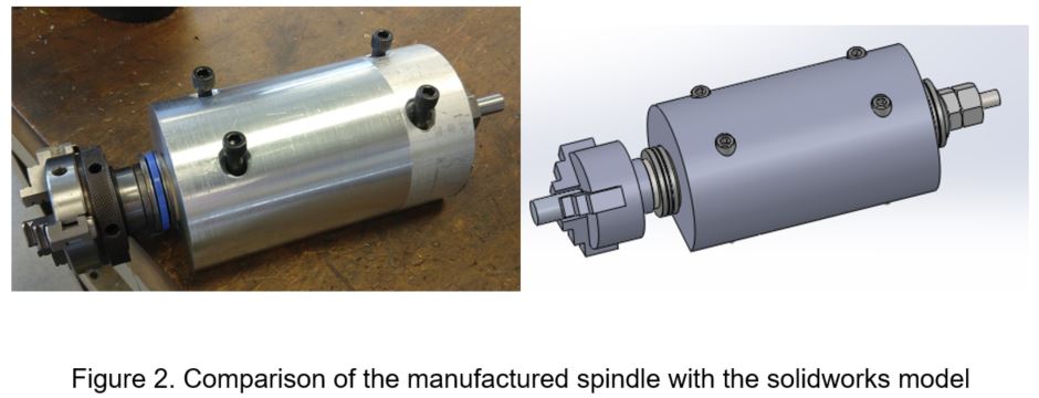
2. Testing
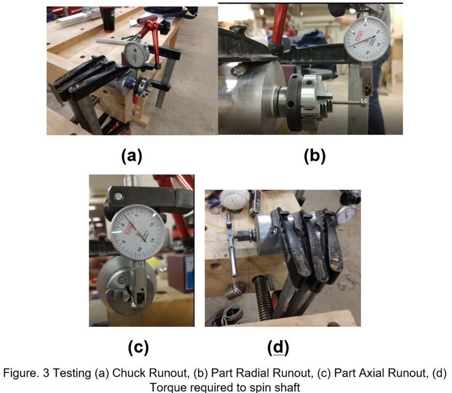
The spindle went to the Hobby Shop and was clamped to a bench with three clamps. A dial indicator measured radial runout, axial runout and stiffness. I measured radial runout at three locations — on the spindle shaft, on the mini-chuck, and on a simulated part tip, using a spherical ball on a post from the dial indicator set to stand in for the part. Further tests measured the torque needed to turn the spindle with and without cutting loads.
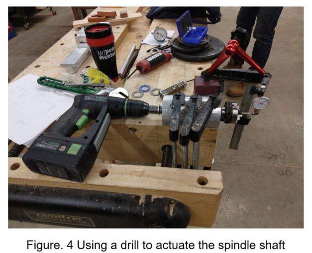
I also drove the shaft with a drill. Spinning it at speed makes the runout error at the part very apparent.
3. Results
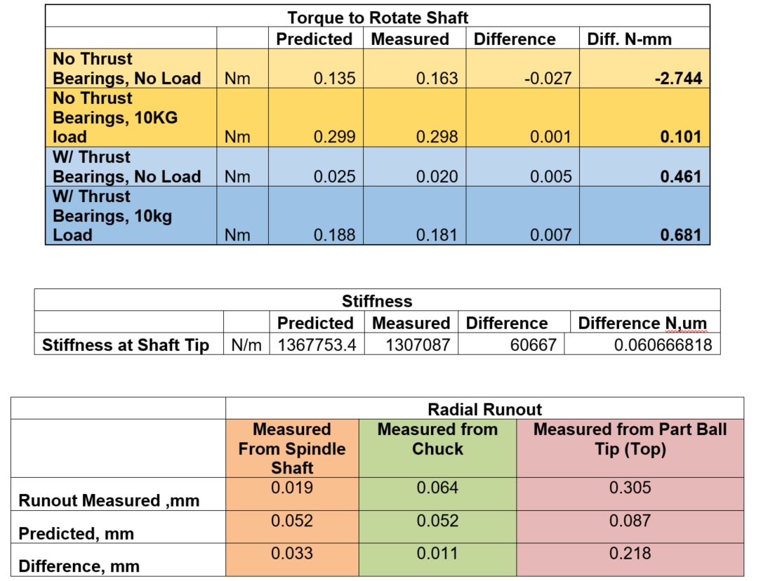
I was pleased with how well the calculations lined up with the measurements. Initially I measured radial runout with the indicator on the hub of the chuck, and was shocked at how bad the readings were given the care I’d put into machining the housing and shaft. On a classmate’s suggestion I measured at other locations too — directly on the shaft, and at the part tip.
| Measured at | Radial runout |
|---|---|
| Spindle shaft | 0.019 mm |
| Chuck | 0.064 mm |
| Part ball tip | 0.305 mm |
The shaft is fine; the chuck is the problem. I had assumed the chuck wouldn’t be a concern, and instead it eats nearly the whole error budget on its own. It now needs to go into the spreadsheets, and I need a more accurate way to attach it to the spindle.
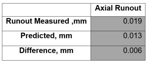
Axial runout agrees reasonably with prediction, which suggests the model in the spreadsheet is right.
The stiffness model needed a correction. It originally predicted nearly ten times the stiffness I measured. Reviewing the class notes, I didn’t fully follow the derivation Professor Slocum was doing with pressure profiles — but an intuitive version works: assume only a small fraction of the bushing is actually carrying the load and elastically deforming. Taking one-third to one-fifth of the bushing’s projected area as bearing the reaction forces brings the model remarkably close to the measurement.
Finally, I estimated the friction torque from the plain bearing sleeves and from their flanges in contact with the shaft. Since I can turn the spindle with my fingertips, I’m satisfied those estimates are about right — and the torque table bears it out.
4. Error budget
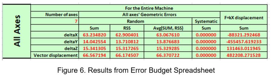
I updated the spreadsheet with the spindle’s radial and axial runout plus the errors from the linear motion module. Surprisingly I’m still inside the 100 µm target, though I’ll keep looking for pitfalls and errors I’ve missed.
Testing the rotary motion module
- LatheDesign_RMH.xlsx — the full lathe design and stiffness calculation — 300.8 MB, too large to host here