Design of a T-Based Lathe, Part 1
The objective this week was to assemble the two linear motion modules and the rotary motion module into a T-based lathe. Next week: test it, and compare the expected facing accuracy against the measured part.
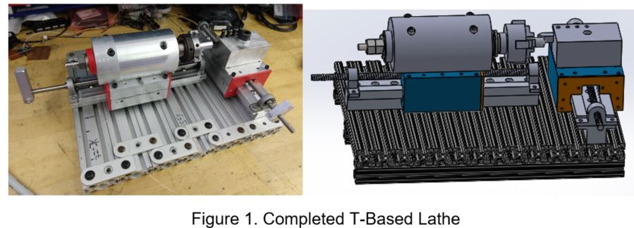
1. Tool holder and leadscrew mounts
Two manufacturing developments this week: a tool holder for the facing tool, and leadscrews on the carriages.
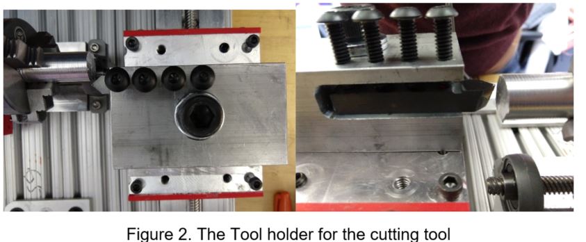
The tool holder is modelled on the ones found on standard machine shop lathes. Four ¼-20 screws clamp the tool during cutting, and a ½-13 threaded hole in the carriage both clamps the holder down and allows the tool angle to be adjusted.
The leadscrews are mounted in the pillow blocks that came with the $13 Amazon set. Not a proper mounting technique, but sufficient here — a production version would get real bearing supports and support blocks. I’d recommend next year’s class include a second rotary motion module, so students build both a spindle and a leadscrew.
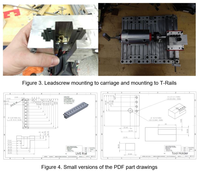
The leadscrew stiffness model builds on work by my classmate Akshay Harlalka for his rotary motion module, and is folded into the error budget spreadsheet. There is currently nothing eliminating backlash between the leadscrew and the carriage — next week I’ll experiment to see whether anti-backlash nuts are actually necessary.
2. Assembly
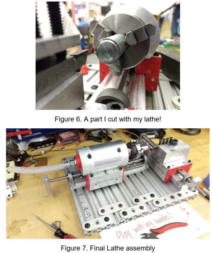
Assembly went smoothly. I used 80/20 extrusion as the base, for stiffness compared to wood and because no sufficiently large piece of stock was available. Assembling it so the cutting forces act with the grain of the extrusion slot makes the separate pieces behave as a single base plate. I did initially assemble the 80/20 in the wrong orientation — visible in the photographs — and corrected it afterwards.
For a motor coupling I used a piece of plastic hose and two hose clamps between the spindle and a hand drill. That lets me hold the drill out of the way, transmitting torque without putting excess reaction force into the bearings. I also repurposed the shaft clamps that came with the leadscrews as makeshift handles — even with proper preload on the carriage bearing pads, the leadscrews turn easily by hand.
3. Error budget
I found last week that some error gain values were incorrectly referenced in the spreadsheet. With those fixed, the budget now predicts 0.66 mm of error in the manufactured part — far above my 100 µm hope, and high enough that I’m still hunting for which sources are actually driving it.
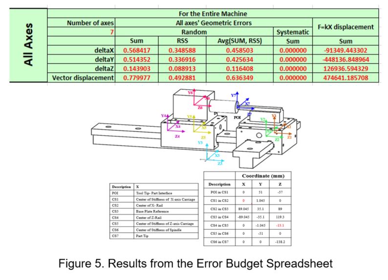
One major source is already clear: the three-jaw chuck. Last week’s rotary module tests put the spindle shaft at only 0.003” of radial runout, but a part clamped in the chuck jaws comes closer to 0.04”. Next week I intend to machine test parts that thread directly onto the spindle shaft, eliminating the chuck entirely.
4. Conclusion
On schedule per the syllabus, and happy with where this is. Next week: more test parts, full testing of the lathe, and finalising the error budget.
The assembled T-based lathe, first cutting test
- LatheDesign_RMH.xlsx — the full lathe design spreadsheet — 300.8 MB, too large to host here