The final report pulls the whole semester together. The objective set at the start — model, design, and build a T-based lathe, in Alexander Slocum’s precision machine design course — turned into practice at three things in particular: building error budgets, propagating error with homogeneous transformation matrices, and designing mechanical components while predicting up front how they would behave.
The full project write-up, including the measured results, is on the T-Based Precision Lathe project page.
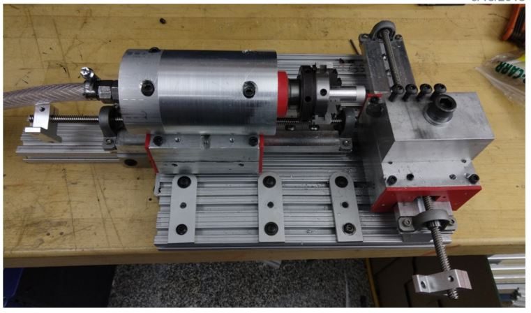
The machine, subsystem by subsystem
In a conventional lathe the spindle is fixed and the tool moves on two axes. In a T-based lathe the spindle rides on one axis and the tool on a second axis perpendicular to it, so the two form a “T”.
- Linear motion modules — boxway slides, chosen off the sketch-model results from weeks 5–7. Each carriage is two plates of roughly 1” aluminum running on Delrin bearing pads, picked for stiffness and low friction, preloaded against the rail with set screws to stop rattle. A cutout along the bottom takes the leadscrew.
- Spindle — built around J3 plain bearings that IGUS representatives brought to class. The housing is turned from 3” 6061-T6 stock with a flat milled for mounting to a carriage; the shaft carries M14×1 external threads so a mini three-jaw chuck can be screwed on, and is preloaded with two disc spring washers and a pair of nuts acting as a locknut.
- Base plate — 80/20 extrusion rather than wood, for stiffness and because no single piece of stock that large was available. Assembling it so the cutting forces act with the grain of the extrusion slot makes the separate pieces behave as one plate.
- Tool holder — modeled on a standard machine-shop lathe tool holder. Four ¼-20 screws clamp the tool; a ½-13 threaded hole in the carriage both clamps the holder down and lets the tool angle be adjusted.
- Leadscrew actuation — mounted in the pillow blocks that came with the $13 screw set. Not a proper mounting technique, but sufficient here; a production version would get real bearing supports. The leadscrew stiffness model builds on work by my classmate Akshay Harlalka for his rotary motion module.
The error model
Error motions from rail parallelism and from applied loads were estimated separately for the linear motion modules and for the spindle, then transformed from each component’s own coordinate frame into error at the part/tool interface using homogeneous transformation matrices. That is what makes the individual subsystem numbers add up to something you can actually compare against a finished part.
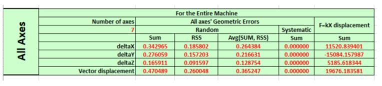
Testing
Cutting forces for facing a 1”-diameter aluminum part with a 1 mm pass work out to 100 N tangential and 70 N each for the radial and thrust directions, using Kalpakjian’s equations. Those are the loads the whole error budget is built against.
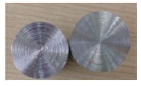
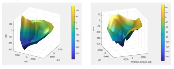
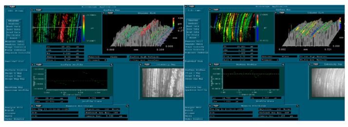
I took facing passes two ways: with the part held in the three-jaw chuck, and with it threaded directly onto the spindle shaft. Splitting the test like that separates the lathe’s own accuracy from the error the chuck contributes. The part faced in the chuck came out visibly wavier than the one threaded straight onto the shaft.
- LatheDesign_RMH.xlsx — the full lathe design spreadsheet — 300.8 MB, too large to host here