Design of a Rotary Motion Module, Part 2
This week: fabricate and test the rotary motion module, and update the error budget — geometric and stiffness — for the completed design.
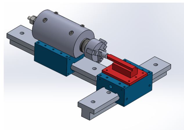
1. Design of the rotary motion module
Knowing time would be tight, I kept the spindle as simple as I could and built it around the plain bearings IGUS gave us in sample kits. I chose the J3 Iglide flanged bearing because it is rated as resistant to unclean environments with a longer working life than its counterparts.
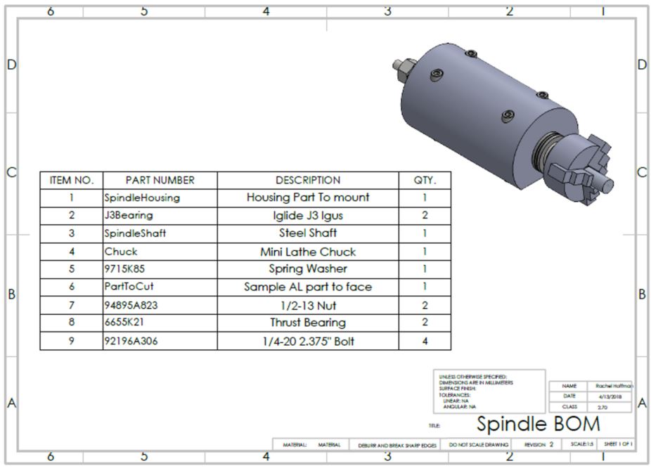
To relieve friction under axial load, there are two thrust washers at either end of the spindle, interfacing between the flanged bearing and the shaft. Two nuts tightened together at the end of the spindle preload the spring washer. Neither the thrust washers nor the plain washers actually need preload to work here, so the spring washer’s preload is chosen simply to keep the shaft in place under longitudinal force.
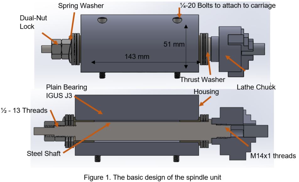
Several features locate the shaft in the housing and the chuck on the shaft. The flanges on the plain bearings are press-fit into the housing and give the axial reference. A flange on the shaft lets the front of the spindle press against the thrust bearing, fixed axially by the spring washer and dual nuts. And a small step inside the chuck means you know exactly how far the spindle is threaded in.
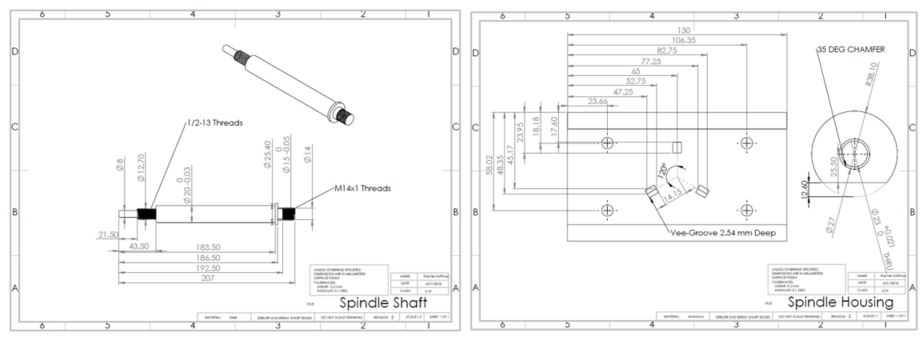
The features needing tight tolerances are the shaft diameter inside the J3 bearings, the shaft diameter seating the chuck, and the housing bore.
2. Stiffness
To get load-induced deflections you need a stiffness model for each component under radial and axial load.
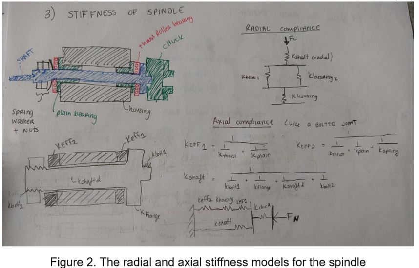
Radial compliance at the centre of stiffness means computing the effective stiffness of the members carrying the cutting force — the shaft in series with the bearing and housing stiffness. Axial stiffness is the shaft acting as a bolt clamping the plain bearings, thrust washers and housing together.
3. Error motions
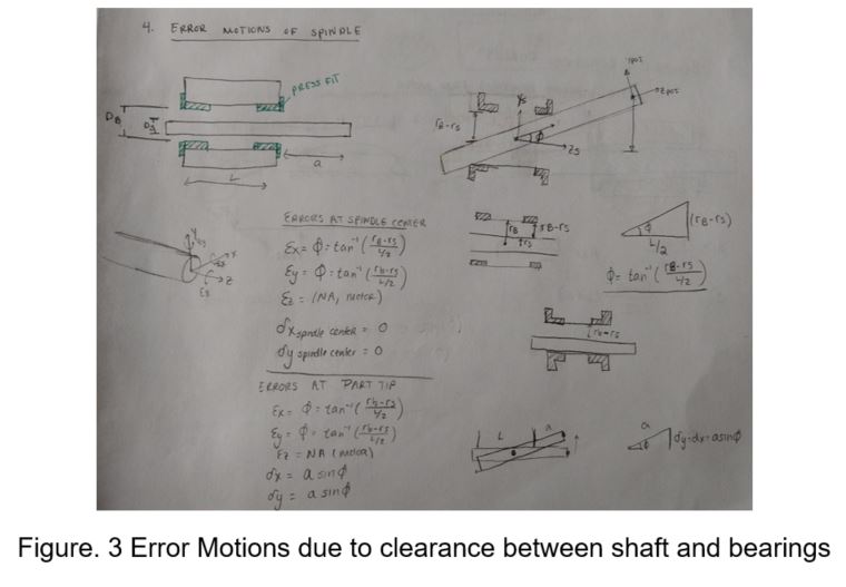
The plain bearing and shaft need a transition fit, so there will be angular error depending on the difference between the bearing’s inner diameter and the shaft’s outer diameter. I expect that to dominate the spindle’s geometric error. The other contributors are the straightness and concentricity of the housing bore, the concentricity of the bearings, and the straightness and concentricity of the shaft.
4. Friction and heat generation
The concern that might undo this design is frictional heat while spinning. To check the spindle won’t jam from thermal expansion, I estimated the expansion of the shaft and the J3 bearings from the power dissipated in friction — and calculated the bearings’ PV value to confirm the cutting loads won’t overstress them.
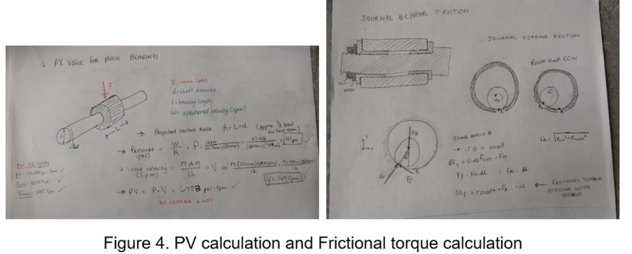
The thermal argument runs: knowing the allowable expansion between bearing and shaft, find the temperature rise that produces it, then use the frictional power to find how long that rise takes.
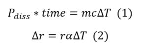
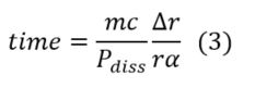
The bearings’ coefficient of thermal expansion was on the datasheet but the specific heat capacity wasn’t, so I estimated it as similar to Delrin.
| Steel shaft expands enough to jam after | about 1 hour |
| J3 bearings expand enough to jam after | 18 seconds of cutting |
Not a comforting result, and a good illustration of why plain bearings aren’t normally used this way. I want to proceed regardless, but with lubricant to cut the friction coefficient and ventilation holes in the spindle to help dissipate heat.
5. Error budget
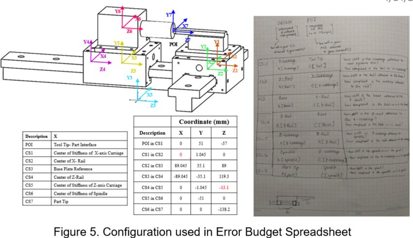
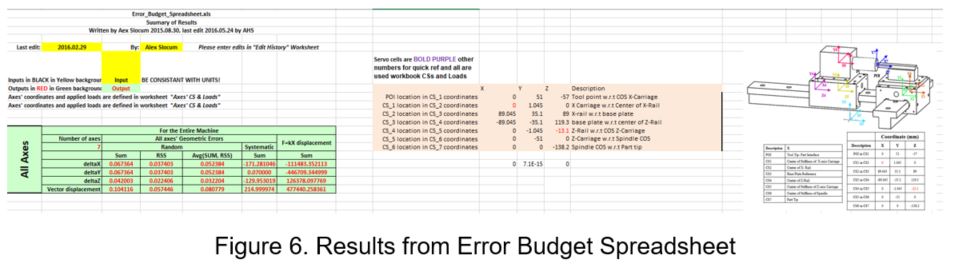
The results summary puts the net vector displacement at 0.08 mm, though there are still gaps. Next week I need to add the stiffness of the rails and of the bolted joints connecting rails to base and spindle to carriage — I expect those to be stiff enough not to invalidate the 0.08 mm, but they belong in the model.
I’m also still working out exactly where each error portion goes and how they combine. Working the HTMs for the linear slide alone made sense at the time; assembling the whole machine is harder. It would help if the spreadsheet had one place to keep a running list of all the random and parallelism errors you can calculate from geometry, and then combined them for you. Perhaps there is and I haven’t spotted it.
6. Machining
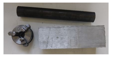
This week I prepared the stock for the spindle — the exact aluminium and steel alloys for housing and shaft are still unknown. I also managed to find one of the old 2.72 mini-lathe chucks to use, which I’m pretty excited about.
- LatheDesign_RMH.xlsx — the full lathe design and stiffness calculation — 300.8 MB, too large to host here