Design of a Rotary Motion Module, Part 1
This week begins the rotary motion module. The T-based lathe needs two distinct ones: a spindle to rotate the part being cut, and the mounting of a leadscrew to the carriages that carry the spindle and the cutting tool. I pursued sketch models of both, to find the manufacturing and design pitfalls while they were still cheap to discover.
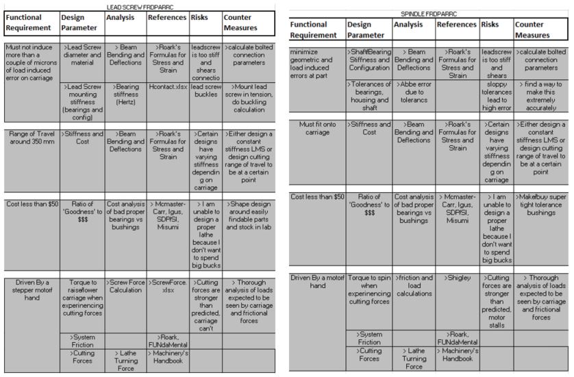
1. Spindle design
The spindle has to resist the high moment and thrust loads that come with cutting. With the expected cutting loads already calculated, the load-induced deflections can be predicted.
High radial and axial stiffness normally means angular contact or tapered roller bearings mounted back to back. The limitation is cost: typical angular contact bearings on McMaster-Carr run $30–300 each and only start at 7/8”. I found 17 × 40 × 12 mm tapered roller bearings on vxb.com for $5 each — the catch being they aren’t ABEC rated.
That is the real choice. Tapered roller bearings that may not hold tolerance but will almost certainly be stiffer than any bushing I can buy or build; or a bushing that imposes greater friction on the spindle and can’t take thrust at all.
I built the sketch model with nylon extrusion acting as bushings, a turned-down aluminium shaft and an aluminium housing.
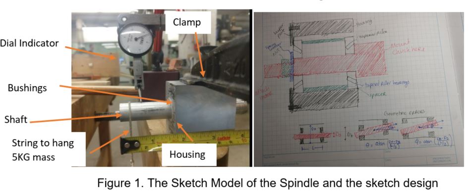
From the sketch geometry I built a spreadsheet predicting angular and translational error at the tip of the part, then tested it against the model. Geometric errors are the angles produced by differences in the diameters of bearings, housing and shaft; load-induced errors come from treating each bearing as a simple support and computing deflection at the point of applied force.
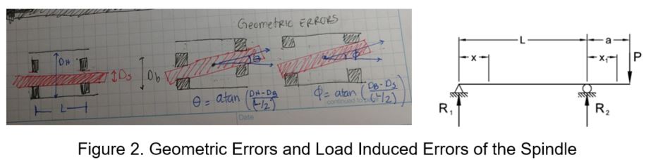
I measured both the geometric and load-induced errors successfully, but the load-induced data was lost when my computer crashed — after the hobby shop had closed, so I couldn’t reproduce it before the deadline.
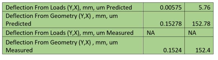
Even so, the headline result is clear: geometric errors dominate. The model predicted 152.78 µm of geometric error at the spindle and 152.4 µm turned up — two orders of magnitude larger than the predicted deflection from loads. Holding tight tolerances on the shaft and housing bearing diameters is therefore what will decide the wobble at the part/tool interface.
2. Leadscrew design
The carriages also have to be actuated. My method is a leadscrew attached to the centre of the carriage. By design and by what stock was available, my carriage and rail are extremely chunky and stiff — the translational z and y stiffness wasn’t even measurable with a dial indicator. That means either the carriage-to-leadnut connection or the leadscrew mount has to be compliant, so it isn’t fighting a far stiffer carriage.
I bored a hole through a single block of aluminium and cut it in half to make two bearing blocks, then turned nylon bushings on the lathe to a transition fit with the leadscrew.
Not wanting to drill into the carriage before the design was final — and short of time to make a proper leadnut bracket — I used the vee-groove test feature as a seat for the leadnut and hot-glued it in place.
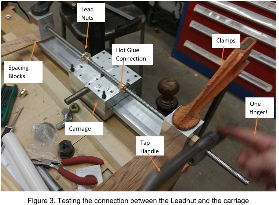
On the first tests, pulling the carriage sheared the hot glue and separated the leadnut. The quick fix was a second leadnut on the other side of the carriage, so one nut is always pushing rather than pulling. That worked beautifully — I could apply a lot of load and still move the carriage easily. Only push and pull forces need transmitting to the carriage, so the hot-glued connection is fine for this purpose.
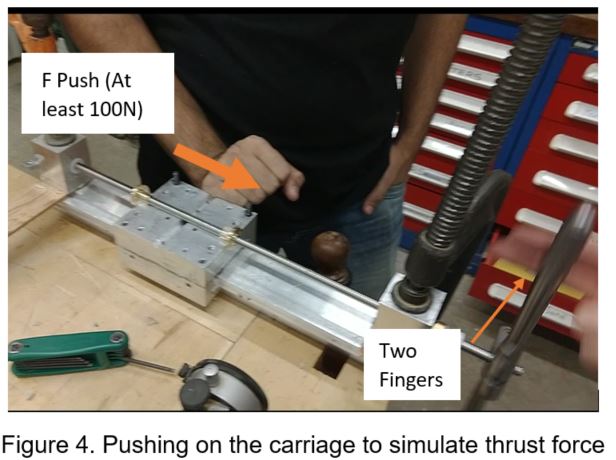
This test was more qualitative than quantitative — the point was to see how the carriage moves with a cheap Amazon leadscrew mounted deliberately inaccurately, and to confirm that mounting the screw badly wouldn’t put undue stress on the carriage. A friend pushed hard on a bolt sticking out of the side of the carriage — at least 100 N — and I could still move the carriage through its full 350 mm of travel with two fingers. Hanging a 10 kg weight from the same bolt made no difference either.
It is not accurate, and it still has backlash. I plan to mill a slot in the top of the carriage for the leadscrew and bolt it down, probably with a spring and a second leadnut to take out backlash. Now that I know the stiffness is completely dominated by the carriage, I can machine a bracket in an accessible location without worrying the screw will bind.
One real problem: nylon bushings support the leadscrew smoothly but take no thrust load at all. I’ll turn down and thread the ends of the leadscrew so thrust bearings can go on with nuts and spring washers at either end.
I also checked buckling, considering four mounting cases.
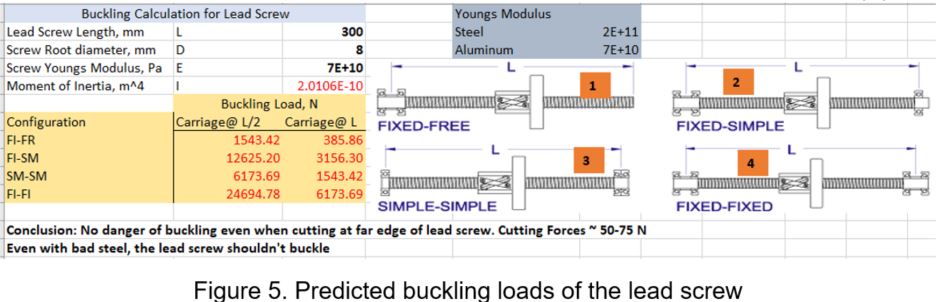
Even in the least stiff configuration (fixed-free) and assuming genuinely poor steel — taking Young’s modulus as aluminium’s — there is still a factor of safety of 5 against the cutting loads.
As a sanity check I compared the leadscrew stiffness model against measured deflection under load.
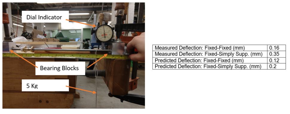
Measured and modelled agree reasonably. I think the remaining discrepancy comes from the nylon bushings and from my having measured with a tape measure and a certain amount of eyeballing — varying the parameters by a few millimetres in the spreadsheet brings predicted and measured into line.
3. Conclusion
These sketch models did their job: they identified the danger zones before I commit to manufacturing the real modules. For the spindle, geometric error is the worry — I am not the best lathe operator, so I’ll have to be creative making the shaft and bearing housing. For the leadscrew, fixing the leadnut securely to the carriage should be manageable; I’ll track the forces the leadscrew misalignment exerts on the carriage and add them to the error budget, and modify the screw to handle thrust.
Honestly, I think the cheap pillow bearings that came with the leadscrew could handle the lathe’s thrust loads perfectly well — but that doesn’t feel like it’s in the spirit of the class.
- RotaryMotionModule_RMH.xlsx — spindle and leadscrew analysis
- Error_Budget_Spreadsheet_RMH.xlsx — the error budget at this stage
- LatheDesign_RMH.xlsx — the full lathe design spreadsheet — 300.8 MB, too large to host here