Design of a Kinematic Coupling for Precise Positioning of a Turntable
Background
Every rigid body has six degrees of freedom, and machine designers routinely need a component held so that it moves in none of them — repeatably, accurately, and without being over-constrained.
In the 1800s James Clerk Maxwell and Lord Kelvin each arrived at what we now call kinematic couplings: deterministic mechanical systems with high positional repeatability and stability that can still accommodate twisting, bending, and temperature variation. A coupling has two platforms, one fixed and one removable, and its defining property is that the removable half returns to exactly the same position every time it is replaced. The two classic forms are the Kelvin clamp — three spheres on one platform against a flat, a conical cup and a vee-block on the other — and the Maxwell system, three spheres against three vee-blocks.
The Maxwell system’s stability comes from where the vee-blocks sit and where each sphere touches them. Following Blanding (Exact Constraint: Machine Design Using Kinematic Principles, 1999): a point on the body along a constraint line can move only at right angles to that line, never along it; any pair of constraints whose lines intersect at a given point is functionally equivalent to any other pair in the same plane intersecting there; the axes of a body’s rotational degrees of freedom each intersect every constraint applied to it; and a constraint removes the rotational degree of freedom about which it exerts a moment.
Each vee-block/sphere pair removes two degrees of freedom, so three pairs should remove all six — but only if they are arranged so those constraints aren’t redundant. Align the vee-blocks so their pairs of contact force vectors form a triangle, and so the bisector of each corner of that triangle passes through both the coupling centroid and its own vee-block/sphere pair, and the system has a stable instant center of rotation.
Design proposal
My research is a multi-track rail system: vertical tracks joined by angular traverse tracks, switched by a novel point system, with carriages moving across the grid to reach many locations quickly. The piece I was working on was the vertical turntable that makes track switching smooth and continuous — and that turntable has to align precisely in nine different orientations.
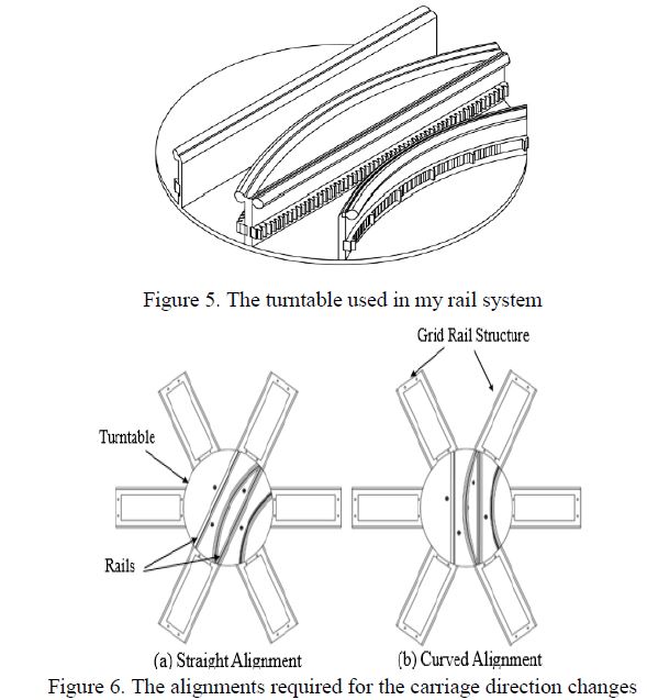
Maxwell couplings looked like a clear improvement over the positioning method the design used at the time. The obvious tension is that a kinematic coupling is designed to not rotate, and this turntable has to rotate on command. I wanted to try pop-and-lock schemes that would let it lift, turn and settle back into the coupling — but with the time available I didn’t think I could manufacture a practical pop-and-lock that worked with the existing turntable. So I scoped the assignment to the coupling itself: a Maxwell coupling that positions the turntable precisely in each of the nine required alignments.
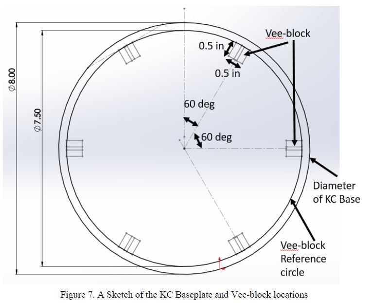
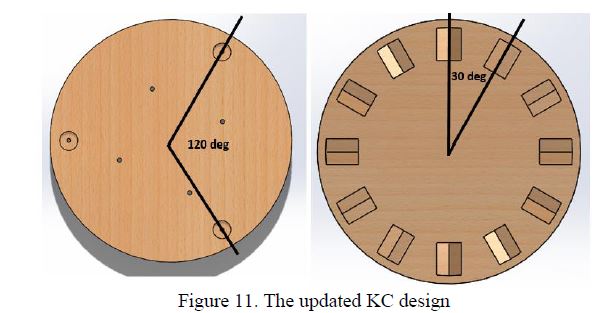
Six vee-blocks, 60° apart — which, by a genuinely convenient coincidence, matched the existing turntable and rail geometry exactly. Those six form two distinct coupling triangles. The top plate carries two sets of spheres: one set with a sphere on the centerline of the straight rail segment, and another set with two spheres at 30° and 150° from vertical, lying along the bisector of the line joining the outer edges of the curved rail segment.
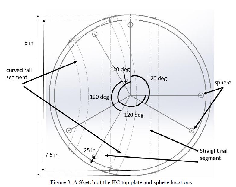
Pairing either vee-block triangle with either the straight-rail or curved-rail sphere set produces every rail connection the system needs.
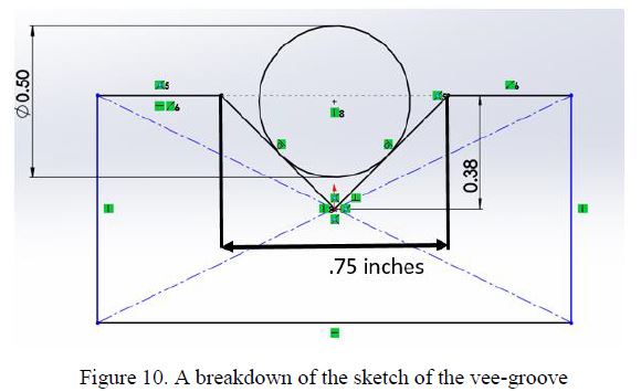
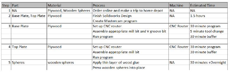
The whole thing is wood: a ½” plywood base so the vee-blocks could be routed straight into the surface, ½” wooden spheres on the top plate, and the top plate routed with a rough outline of the rails so the coupling doubles as a visual aid for the rail system. A 45° vee groove ¾” wide at its mouth and 0.375” deep gives secure sphere contact.
Fabrication
Reviewing the design before cutting, I found a real problem: with two sets of balls and only one set of vee-grooves, the set of balls not sitting in grooves would interfere with the bottom surface. I fixed it by adding a second set of vee-grooves and dropping one set of spheres, and moved to ¾” spheres, which suited the scale of the plates better. The original concept survived intact.
Manufacturing went nearly to plan. The first attempt at the base plate used a vee-groove bit only ½” across at its widest, which cut a groove that was irregular and far too deep to seat the top plate properly.
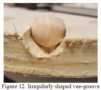
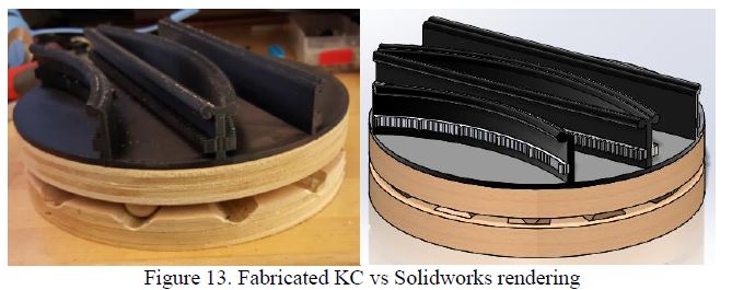
Swapping to a 1.5” vee-groove bit and re-routing the base fixed it. I routed the top plate, finished the holes with an 11/64” drill bit, press-fitted hobby-shop dowels into the top plate and into the flats on the ¾” spheres, glued them, and left the assembly 24 hours to cure before attaching the 3D-printed rail plate with four 10-32 × ¾” machine screws.
Testing
A level checked flatness before the rail segment went on.
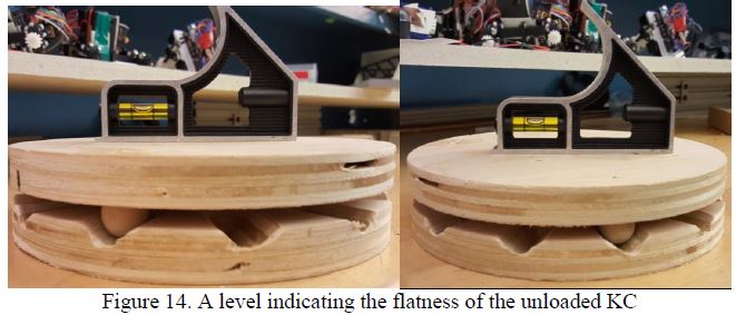
Unloaded, the coupling is reasonably flat in one orientation; rotating the level showed it isn’t exactly level, which could be the top of the coupling or simply the desk underneath.
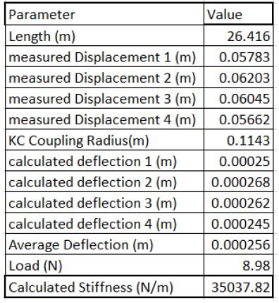
Measuring displacements of a fraction of a millimetre with calipers was hopeless, so I used a laser to amplify them. A pointer taped to the top plate and aimed down a 2.48 m hallway in the basement of Building 1 turns a tiny angular displacement at the coupling into a measurable spot movement on the wall — Abbe error working in my favour for once. The amplification is the hallway length over the coupling radius, 114.3 mm.
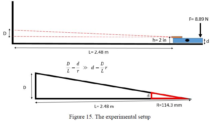
The pointer was aligned parallel to a bisector of the coupling triangle and its rest position marked with no preload beyond the coupling’s own weight. A 2 lb aluminium block (8.98 N) placed directly over one of the three balls tilted the top plate.
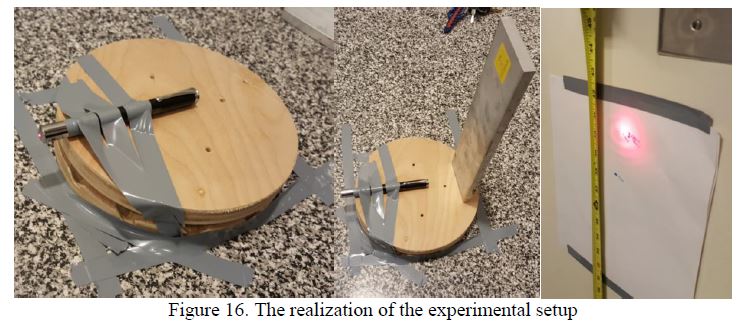
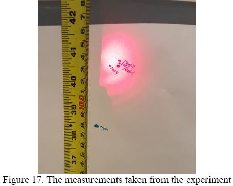
Repeatability used the same rig with the load removed: lift the top plate off and replace it four times, measuring where the laser lands each time relative to trial one.
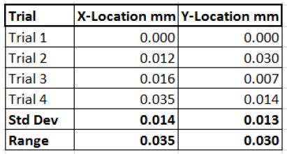
The scatter in both axes was well beyond what I expected. I suspect a good share of it is the rig rather than the coupling — there is no guarantee the base plate stayed put while the top plate was being lifted on and off.
Both experiments carry real uncertainty. The laser diverges over 2.48 m, so the true centre of the spot is a judgement call; taping the pointer to the coupling doesn’t guarantee it is aligned with the coupling’s true centre; the calipers resolve 0.01 mm; and the coupling is handmade from plywood, which varies.
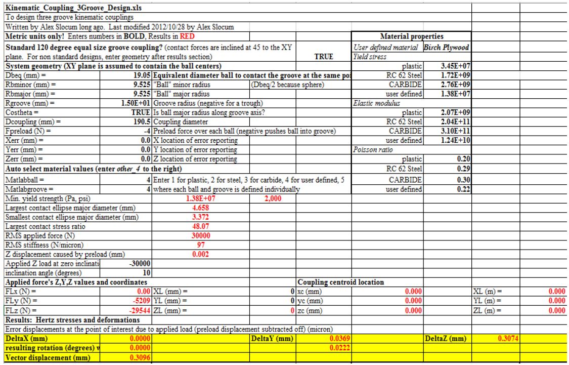
Against Professor Slocum’s kinematic coupling design spreadsheet, my measured stiffness came out well below prediction and my displacements above it. I attribute most of that gap to the experimental setup rather than the coupling.
Conclusion
A good introduction to designing and building a kinematic coupling — I came out of it with the underlying physics and maths properly in hand, and intend to keep using them in my research. The obvious next improvement is the mechanism I scoped out at the start: some way to lift, rotate and re-seat the top plate so the coupling can serve all the rail alignments the network needs.