Design of an Elastically Averaged Coupling, Part 1
At first glance elastic averaging looks like over-constraint. Exact-constraint design places one intentional contact point per degree of freedom — that’s a kinematic coupling. Elastic averaging deliberately uses many contact points, typically more than six, which ought to over-constrain the system. It doesn’t, provided one side of the interface is made reasonably compliant and the other sufficiently stiff, because then the interface behaves as a collection of springs.
The classic illustration is pin-in-hole. Force many rigid pins into an equal number of rigid holes and the pins see enormous stress fighting holes that are imperfectly made and imperfectly placed. Design the pins to deform enough to find the misaligned holes without yielding, and the same interface works — with the averaging over many contacts doing the job that exact placement did before.
Because that spring model is analysable, an elastically averaged coupling can be predicted rather than just built and hoped for. This week’s assignment was to design one and compare predicted stiffness, accuracy and repeatability against the real article.
Design process
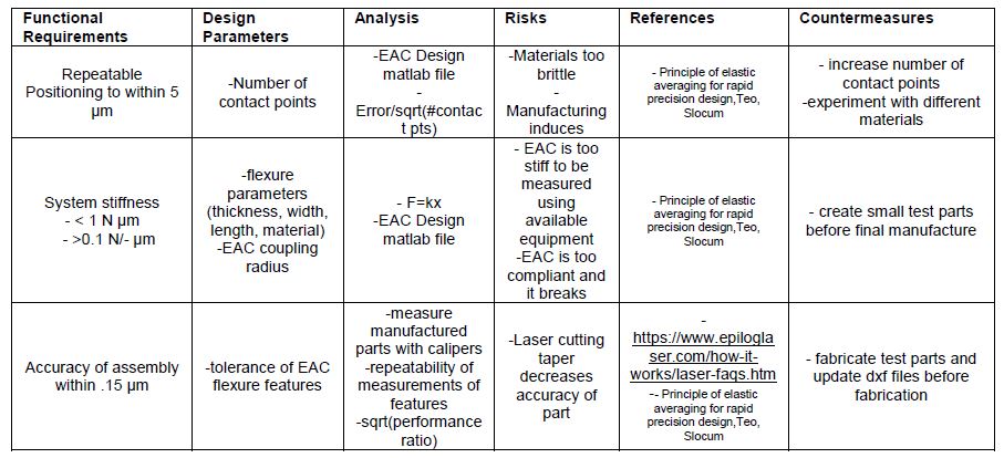
Two things drove the design: understanding the physics properly, and making it scalable to the T-based lathe later in the term. That pushed the material choice toward aluminium dowel pins in MDF — cheap, and laser-cutting MDF is a fair analogue for the waterjet-cut aluminium or steel I expect to use on the lathe itself.
I worked up three concepts, all manufacturable on a laser cutter or waterjet: two cantilever beams mounted at opposite ends of the dowel pin; solid beam flexures following the model in Teo and Slocum’s elastic-averaging paper; and compliant pins that put the compliance into the pin rather than the plate.
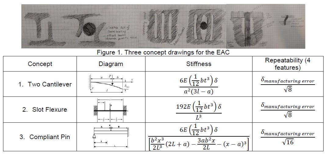
I went with the second — slot flexures. Concept 1 worried me because the free-floating ends of the cantilever beams looked liable to snap off in use, and concept 3 because of how large the coupling would have to be to cantilever and secure the compliant pins properly. Both are realisable with more time.
The scalability requirement got met by building a second EAC into the design and using it as a locating feature: a clamp holding the laser pointer stands in for the lathe spindle, coupled to a top MDF plate, which is in turn coupled to a bottom MDF plate. That mirrors mounting a spindle to a rigid structure and then mounting that structure to the lathe. I also kept every feature modular — the analysis code takes an arbitrary number of flexure features with arbitrary geometry, so design decisions still open on the lathe don’t invalidate it.
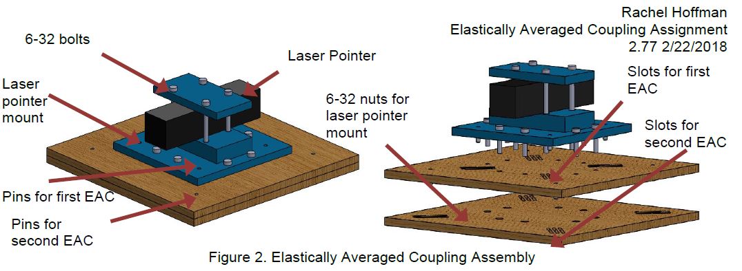
Manufacturing and assembly
Brittle MDF meant the coupling had to be big enough to handle and test without fear of breaking it — at least 7” × 7”.
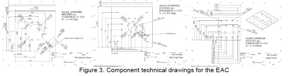
Laser cutters taper thick material, so as with the kinematic coupling I trialled power, speed and pass count; a single pass at 100% power and 4% speed came out best here. The mock spindle mount holding the laser pointer is 3D printed — it isn’t a critical module of the coupling, so simulating it that way was acceptable. Aluminium pins and 6-32 nuts were superglued into their press fits as insurance.
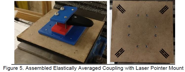
Testing
A MATLAB model written during the design predicts stiffness and repeatability as flexure thickness, length and the rest are varied. It defines the flexure geometry and computes x-axis, y-axis and rotational stiffness by transforming the spring forces into x, y and θ.
Accuracy. I had designed the coupling without a reference feature to measure accuracy against — so I went back to the hobby shop and cut another one, essentially the same but with five extra slots (nine pin-slot features total) and a circular hole in the centre of each plate. Two concentric circles give something to measure.

So the centres of the two feature patterns should sit within 0.24 mm of each other. Testing meant mounting the bottom plate in the mill, finding its hole centre with a centre-finder, zeroing the mill’s x-y there, then placing the top plate and finding its hole centre relative to the first.
Raw measurement: 0.37 mm out in x and 0.25 mm in y — worse than predicted. But the reference holes are themselves manufactured features with their own error. Measuring them against the top and left edges of each plate showed the holes are off-centre by 0.16 mm in x and 0.20 mm in y. Account for that and the coupling’s own accuracy is 0.21 mm in x and 0.05 mm in y.
| Predicted radial accuracy | 0.24 mm |
| Measured, reference-hole error accounted for | 0.21 mm |
| Measured, ignoring reference-hole error | 0.44 mm |
Stiffness. The coupling went on the mill with a dial indicator in the collet, zeroed against the left side of the top plate. A digital scale told me I could produce about 50 N consistently with both thumbs; pressing the centre of the opposite side and reading the indicator, ten times per axis, gives stiffness straight from F = kx.
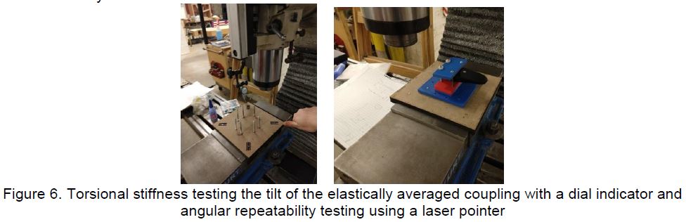
Rotational stiffness used Abbe error again — laser pointer on the coupling, thumb pressure of roughly 20–25 N against one corner, ten trials.
Repeatability came from the same rig: the standard deviation as the top plate is removed and re-engaged. Angular repeatability was measured with the laser spot 630 cm away, ten removal cycles, giving 0.1 mrad (0.006°).
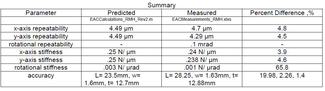
Everything except rotational stiffness landed within about 5% of the model.
Conclusions
The measurements agreeing this closely with the model was the satisfying part, and it means I can use the same analysis to design most or all of the elastically averaged couplings on the T-based lathe — the MATLAB is deliberately modular enough to take any number of flexures with varying parameters.
If I repeated this I would put flanges on the top of the coupling so a known weight could be hung from it, or use a force gauge, rather than relying on thumb pressure calibrated against a scale. Since the measured data agreed with the analysis anyway, I think the model is right despite that imprecision in the applied force.
MDF impressed me. I half expected the flexures to break despite the analysis saying they wouldn’t, and they held up to repeated rigorous testing while the system stayed stiff and repeatable. Unlike plywood its strength isn’t directional, it’s far less brittle than acrylic, and it comes off the saw with a smoother surface finish than wood — which sidesteps the problem I had with wooden balls in last week’s kinematic coupling.