Design of an Elastically Averaged Coupling, Part 2
This week was for reflecting on the work so far and picking up any testing left undone.
I’m happy with the previous three weeks — the kinematic coupling and the elastically averaged coupling both got rigorous testing, and the reports follow the full loop of modelling, predicting, building, testing and comparing. The main thing my peers wanted improved was my understanding and testing of the EAC’s accuracy, so that is what I went after, along with tidying up.
Four things:
- Update the kinematic coupling write-up to address reviewer comments
- Redo the EAC accuracy test after the class discussion, and clarify the write-up
- Provide a handwritten derivation of the predicted accuracy and stiffness model
- Move the MATLAB EAC analysis into a spreadsheet
1. Kinematic coupling — reviewer comments
The staff’s main comment was that stiffness should have been predicted with a spreadsheet. It was: the KC analysis folder holds two, Professor Slocum’s and one I wrote myself to work through the maths behind kinematic couplings. I updated the write-up to make clear that the parameters were estimated in a spreadsheet first and measured afterwards.
I also worked out why the measured stiffness came in about 20× below prediction. Playing with the coupling, I noticed the flats on the wooden balls were sometimes not perfectly flush with the plate. Watching how the balls moved, I’m confident that manufacturing defect is the main source of the discrepancy — not the model.
2. Redoing the EAC accuracy test
I went back to the hobby shop and made another coupling: essentially last week’s design with five extra slots, for nine pin-slot features, plus a circular hole in the centre of each plate. Two concentric holes give a reference the accuracy can actually be measured against. Expected accuracy is 0.24 mm between the centres of the two feature patterns.
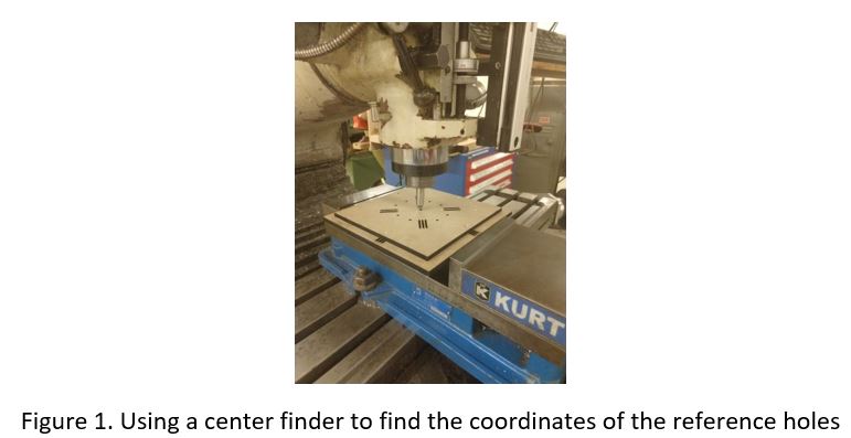
Mount the bottom plate in the mill, find its hole centre, zero the mill’s x-y there, then place the top plate and find its hole centre relative to that.
Raw result: 0.37 mm out in x, 0.25 mm in y — worse than predicted. But the reference holes have their own manufacturing error, and if the feature you measure with is inaccurate the coupling will look worse than it is. Measured against the top and left edges of each plate, the holes sit 0.16 mm off in x and 0.20 mm off in y.
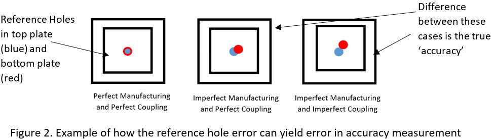
That diagram is the argument: the difference between the second and third cases is the coupling’s real contribution, and everything else is the reference feature.
| Predicted radial accuracy | 0.24 mm |
| Measured, reference-hole error accounted for | 0.21 mm |
| Measured, ignoring reference-hole error | 0.44 mm |
3. Handwritten model derivation
I wrote out a clear, detailed derivation of the model used to estimate the EAC’s stiffness and displacements, and would welcome feedback on it — part of what I want out of this semester is to turn the work into a learning tool that future precision design engineers can use to get the FUNdaMentals down.
4. MATLAB into a spreadsheet
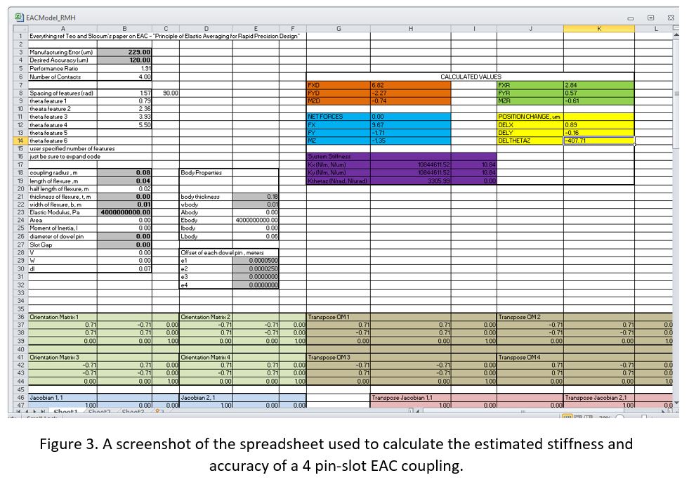
Conclusion
I’m genuinely happy with the work so far. My designs may not be especially adventurous, but my preferred way to learn is to master the basic cases — the ones with plenty of examples and resources behind them — and then move to more complicated designs from a solid footing.