Design of a Linear Motion Slide, Part 1
Requirements
This week starts the analysis and design of the linear motion system that will become the axes of the T-based lathe. Two requirements sat at the front of my mind throughout: whether I could actually make the thing, and enough stiffness that the axes barely deflect under cutting loads.
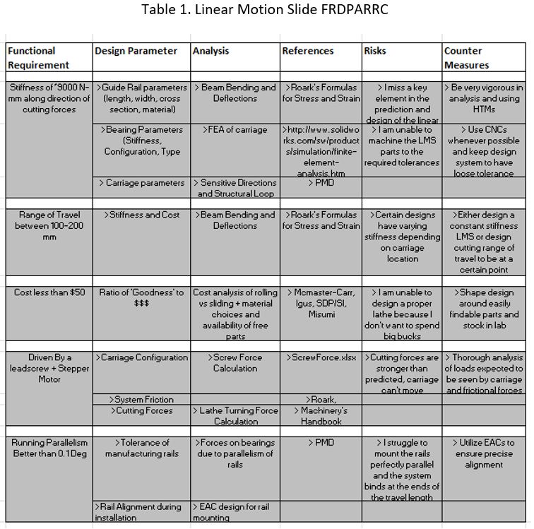
I researched the cutting forces expected when turning 1” aluminium with a power drill as the spindle, and found published values ranging from 40 N all the way to 170 N. I took the high end as the target, to keep the design conservative.
I knew I wanted a leadscrew and stepper motor driving both linear axes. Working from the specifications of common steppers, a Nema 17 with 59 N·cm of torque and an 8 mm leadscrew provides enough force to move the carriage against the cutting loads plus estimated friction. As the analysis develops I’ll fold in system efficiency and a proper derivation of the frictional forces, to be sure the motor still has the torque during an actual cut.
Concept analysis
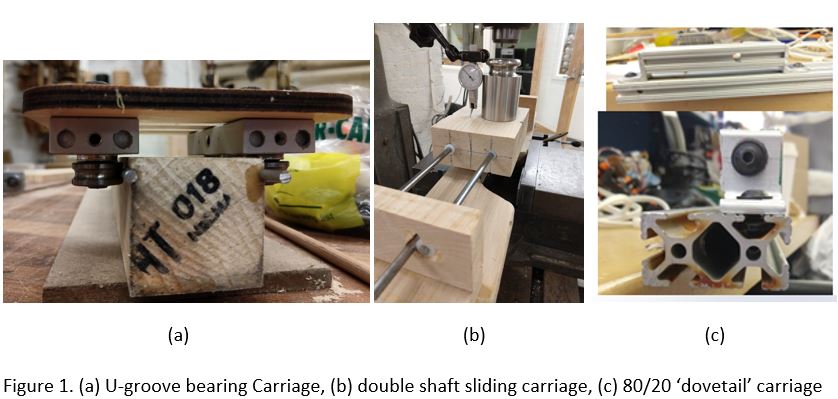
Three linear motion systems, each with a first-order model predicting the error motions the carriage would undergo while cutting:
- U-groove bearings — built around a nice set I found in my lab
- Double shaft and leadscrew — the classic configuration
- Dovetail or T-rail — made from 80/20 and T-nuts
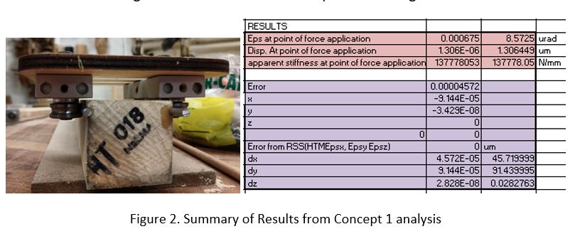
For concept 1 I worked through deflections from the forces on each bearing plus the geometric error motions, and ran a quick Hertz contact stress check to confirm the rails and bearings wouldn’t fail under the expected loads.
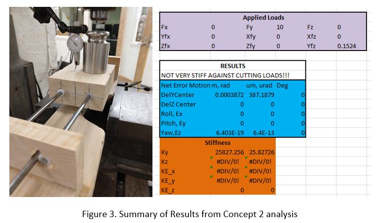
For concept 2 the rail deflections dominate, so I computed the forces on each bearing under different loading conditions, then the rail deflections and stiffness, and finally the net displacement at the carriage centre.
For concept 3 I treated each section of the carriage as a cantilevered beam under distributed loading, combined with the stiffness of the bearing pads — ⅛” Teflon strips, chosen for low friction and high compressive modulus.
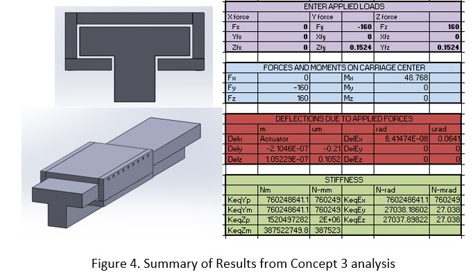
Concepts 1 and 3 both look capable of standing up to the cutting forces in the right configuration. I have most confidence in the concept 3 analysis, because it rests on simple beam bending and bearing pads rather than anything exotic.
What the sketch models taught
Concept 1. I milled slots along both sides of a wooden beam and epoxied aluminium rods into them, clamped straight and flat. What I didn’t foresee was how much the epoxy would leak — enough residue built up on the rails to interfere with the carriage. Residue aside, the bearings were genuinely impressive: smooth, and the concept clearly has promise. My remaining worry is that bearing position has to be very precise to get the preload right, and too little preload risks a large moment popping the bearing over the rail.
Concept 2. A perfect demonstration of how parallelism error makes a carriage bind. Despite real care drilling the holes through the carriage block, one came out at an angle and bent its shaft dramatically. Mounting the shafts in separate adjustable clamps, bolted down after the carriage is in place, would avoid it. This was the least stiff of the three.
Concept 3. No time to make a true T-rail or dovetail, so I approximated it with two pieces of 80/20 — one as rail, one as carriage — and T-nuts as sliding bearings. That highlighted exactly why you need a bearing pad: the moment you tighten the T-nut enough to preload the carriage, friction stops it sliding at all. Coating the underside of a few T-nuts with bearing pad material and seeing whether you can then preload and slide would be an interesting experiment. The ease of assembly and the robustness against applied moments both impressed me.
Stiffness and straightness testing
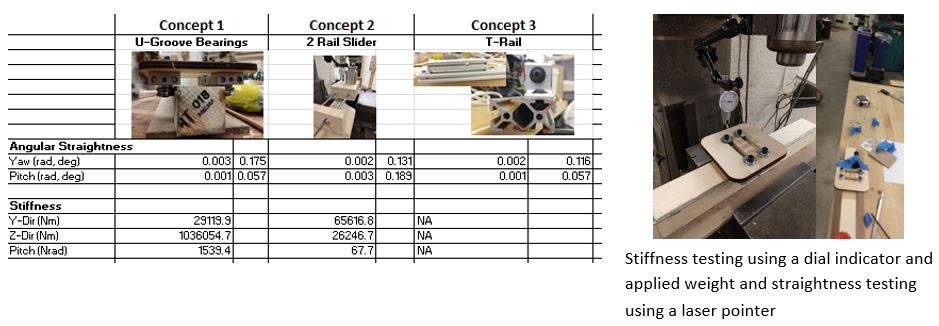
Concepts 1 and 2 went on the mill under a dial indicator, tested under various loads.
| Predicted | Measured | |
|---|---|---|
| Concept 1, z-direction | 137 N/µm | ~1 N/µm |
| Concept 2, y-direction | 25.8 N/mm | 26 N/mm |
The u-groove design is stiffer and more forgiving of manufacturing defects than the double-rail slider, as expected. Its two-order-of-magnitude stiffness miss I attribute largely to having preloaded the bearings by feel rather than by calculation.
Concept 2 matching prediction to within a percent, on the other hand, I’ll take. It is always a good feeling when the measurement lands on the number. Concept 2 is easier to analyse accurately but much less stiff, which makes it harder to justify in a high-force application. I didn’t measure concept 3 — that sketch model was more useful for getting a feel for preload friction and for how carriage length trades against width.
Two other things worth noting
Linear bearings and u-groove bearings are dispiritingly expensive, but I found a pre-packed linear motion slide kit on Amazon for $40. The bearings aren’t good — it’s aimed at 3D printers, so it likely won’t take high loads — but I ordered one to play with, and I think I want to use its leadscrew and leadnut in the lathe.
I also stumbled on Igus, whose catalogue documents every parameter you could want for designing your own linear system: installation, adjustment, stiffness, friction coefficients. Good customer service, roughly 24-hour delivery, and they send samples. I’m hoping to get one of their linear motion products to try.
Conclusion
I feel considerably better about designing a linear motion slide after this week, and most confident about the T-carriage analysis and design. I think I can build it entirely from stock bar and sheet bolted together, which keeps the cost down. Working out how to preload the carriage onto the rail properly is the next problem, but this system should give the stiffness I need while staying robust against my own manufacturing errors.
- ConceptExploration_RMH.xlsx — FRDPARRC, error budget, stiffness and cutting-force analysis — 143.5 MB, too large to host here