Design of a Linear Motion Slide, Part 2
The goal this week was to finalise the linear motion module design and evolve the analysis that predicts its stiffness, accuracy and repeatability.
1. Cutting forces
Following the analysis in Kalpakjan and Schmid’s Manufacturing Engineering and Technology (chapters 21 and 23), I built a spreadsheet predicting the cutting forces the slide will see.
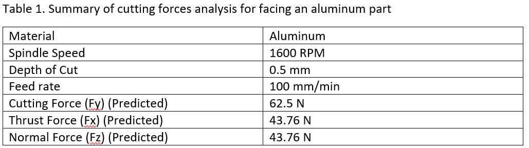
Those forces feed the axis error apportionment. For the lathe to hold 100 µm of total allowable error, the load-induced deflection from bearings and structure on one axis gets 19.9 µm. Working back from the expected forces and that allowance gives a net system stiffness requirement of 3834 N/mm — a reasonable target.
2. Carriage geometry and stiffness
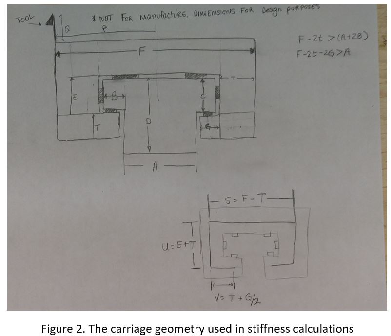
Having settled on a boxway and T design, I built a spreadsheet that predicts carriage stiffness about and along each axis directly from the geometry, so dimensions can be changed in CAD and re-evaluated quickly.
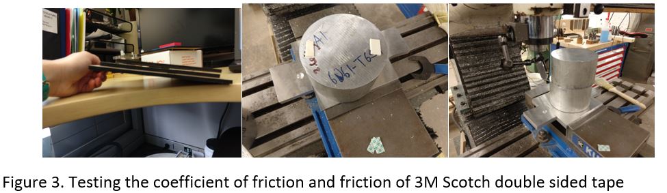
Bearing pad material took real thought. I found some 3M Scotch foam double-sided tape that adheres well to aluminium and whose backing is quite slippery. Two pieces of MDF and a tilt test gave the friction coefficient from the tangent of the sliding angle — 0.12. Stiffness came from sticking two pieces to an aluminium block and measuring deflection under an extra 2.6 kg block: 204.7 N/mm, nowhere near stiff enough for this slide.
I then found UHMW polyethylene in my lab. Using the material properties from MatWeb, a thin square of UHMW calculates out at 138 N/µm — which is the number the design needed.
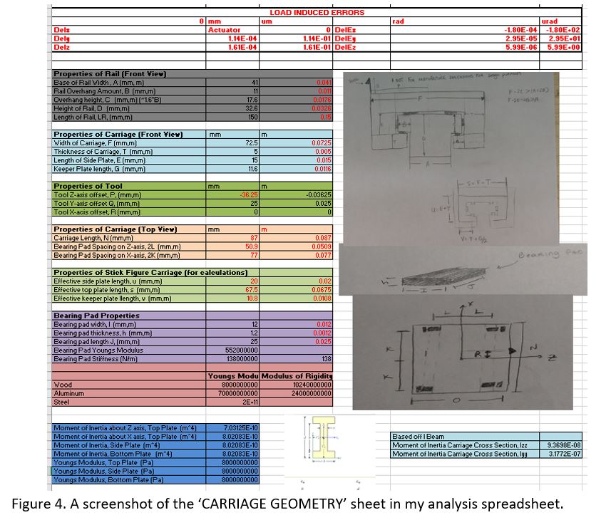
Load-induced errors come from dividing the forces at the carriage’s centre of stiffness by the carriage stiffness about that axis. Geometric errors come from the manufacturing and assembly tolerances — since the carriage is preloaded, they are dominated by how the slide is mounted and by parallelism error from flatness. I estimated the geometric error about and along each axis, then used homogeneous transformation matrices to carry each one through to the tool tip in the reference frame, computing both the linear stack-up and the RMS and taking the expected error as the average of the two.
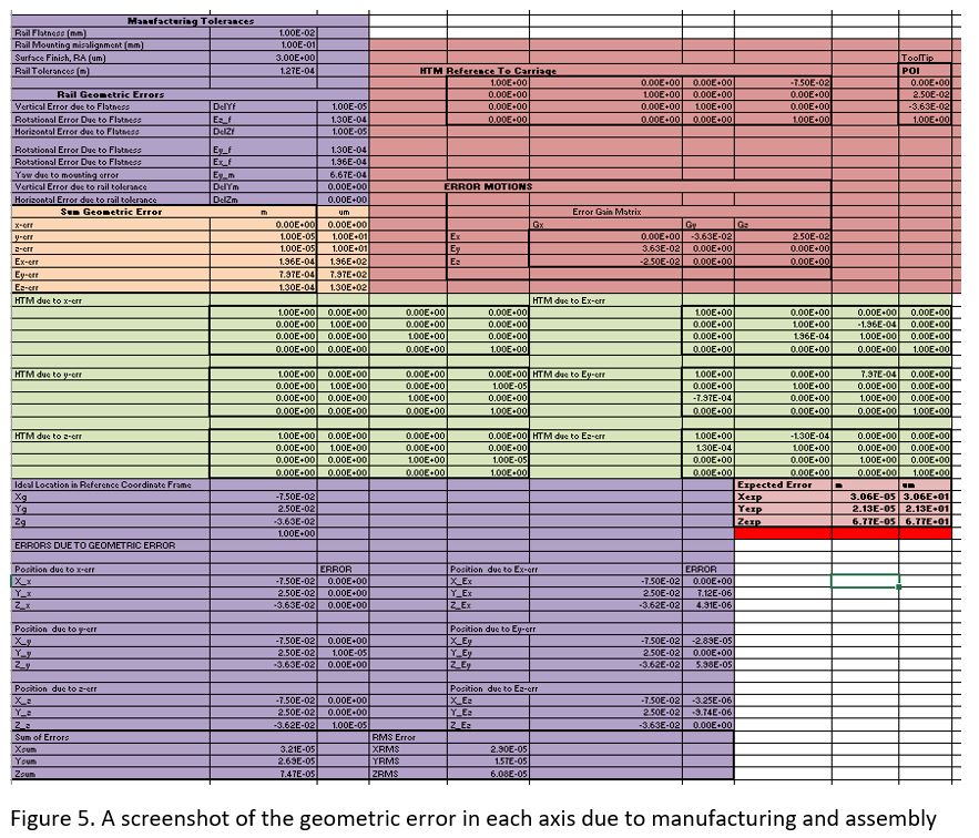
So the expected accuracy of the slide is the sum of the geometric and load-induced errors, and its repeatability is the load-induced deflection alone.

Geometric error dominates, and will eat nearly the whole error budget. Going forward I’ll add reference features to guarantee the two linear systems end up perpendicular.
3. Design and manufacture
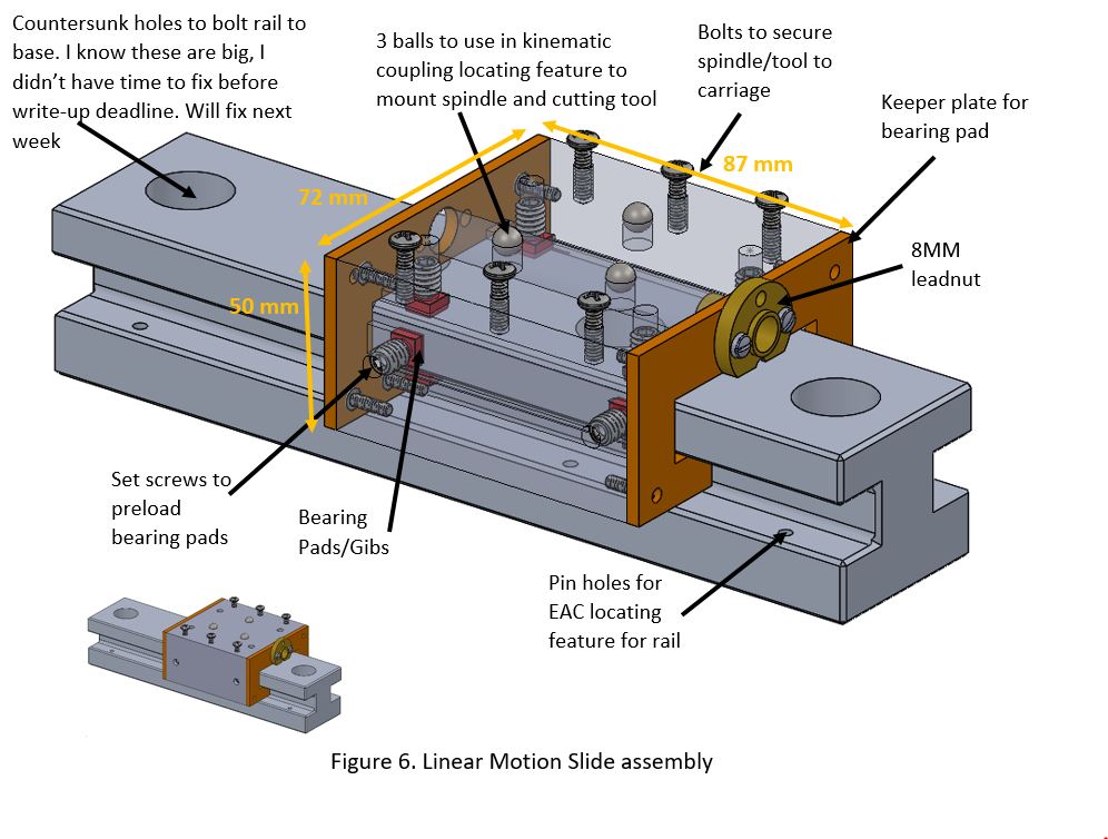
Several features are worth calling out. The Tivar squares double as bearing pad and gib — by sizing the set screw almost as wide as the pad, the pad preloads against the rail without uneven pressure. Three spheres act as kinematic coupling components to locate the spindle and tool; here the spheres and grooves only locate, with bolts providing the attachment stiffness. And two keeper plates bound the pads, which sit in slots milled into the inside faces of the carriage, so they can’t slide out during assembly.
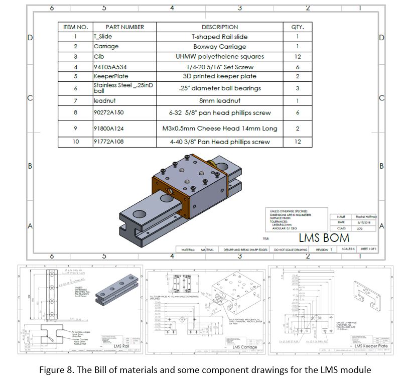
I had intended to machine the carriage from a single piece of aluminium, but with the schedule pressing I couldn’t find stock large enough to start immediately. The choice was to redesign the carriage around available stock, or keep the dimensions and modify it to be made from two pieces. I took the second option so machining could start straight away.
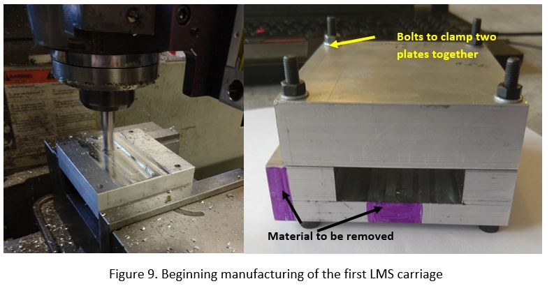
Two identical 25 mm × 90 mm aluminium plates got four corner clearance holes on the CNC mill so they can be bolted together and machined as one piece, and I milled the “T” into one of them. Next is finishing the carriage outline and adding locating pins so the halves can be separated, machined individually and reassembled repeatably.
4. Conclusions and thinking ahead
The past two weeks have been stressful. I felt genuinely behind on the error analysis, and I’m not the fastest machinist. The linear motion module feels better now, and I’m hoping to use spring break to gather my thoughts.
I’m torn about how to proceed next week: either manufacture two complete slide assemblies and test them roughly, or thoroughly build and test one and take the time to reflect and improve the design before making the second. If my classmates feel the same, perhaps we can build and test a single assembly properly and make the second over spring break.
- Week 6 appendix — full drawings and analysis (PDF)
- Stiffness derivation — handwritten derivation of the carriage stiffness equations (PDF)
- LMS_Analysis_RMH.xlsx — cutting forces, error apportionment, carriage geometry and T-slide analysis — 142.1 MB, too large to host here